LMV
Series
Technical
Instructions
Document
No.
LV5
‐
1000
SCC
Inc.
Page
5
Section
6
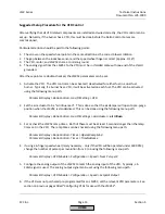
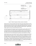
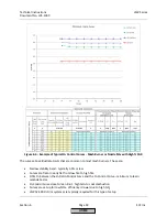
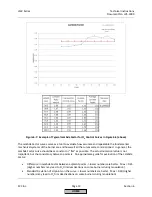
4.
O
2
Control
‐
This
is
the
setpoint
of
the
O
2
trim
system
for
each
point
on
the
curve
except
Point
1.
This
is
also
commonly
referred
to
as
the
“trim
curve”.
5.
O
2
Alarm
‐
This
is
the
rich
O
2
limit
for
each
point.
Every
Fuel
‐
Air
Ratio
Curve
point
including
Point
1
must
have
a
corresponding
O
2
alarm
point.
This
is
also
commonly
referred
to
as
the
“rich
curve”
or
“rich
alarm”.
6.
O
2
Max
Value
‐
This
is
the
lean
O
2
limit,
and
is
a
single
value
for
all
points.
This
is
also
referred
to
as
the
“lean
alarm”.
7.
Lambda
Factor
‐
A
value
that
is
learned
by
the
LMV52
for
each
point
on
the
curve
except
Point
1.
This
value
is
learned
when
the
O
2
control
curve
is
being
set,
and
is
based
on
how
the
measured
%O
2
responds
when
the
burner
is
being
transitioned
from
an
O
2
Ratio
Control
point
to
the
O
2
Control
point
during
O
2
Control
commissioning.
This
value
represents
how
much
the
air
flow
needs
to
be
changed
to
get
a
change
in
the
measured
%O
2
,
and
is
essentially
the
"signature"
of
the
burner
from
an
O
2
trim
perspective.
8.
Fuel
Rate
–
This
is
the
percentage
of
high
fire
fuel
flow
and
is
also
referred
to
as
the
firing
rate.
This
is
also
the
same
as
the
"Load"
number
seen
during
Ratio
Control
Curve
commissioning.
For
a
10
‐
to
‐
1
turndown
burner,
high
fire
would
be
100%
and
low
fire
would
be
10%.
For
a
4
‐
to
‐
1
turndown
burner,
high
fire
would
be
100%
and
low
fire
would
be
25%.
For
O
2
trim
systems,
it
is
very
important
that
the
fuel
rate
(load
number)
matches
the
actual
fuel
flow
to
the
burner
within
+/
‐
3%.
9.
Air
Rate
‐
When
no
O
2
trim
is
taking
place
(running
on
Ratio
Control
Curve),
the
air
rate
is
the
same
as
the
fuel
rate.
This
is
also
known
as
the
air
flow.
For
example,
a
10
‐
to
‐
1
turndown
burner
running
at
Point
5
on
the
Ratio
Control
Curve
will
have
a
fuel
rate
of
50%
and
an
air
rate
of
50%.
If
the
O
2
trim
is
engaged
and
the
O
2
sensor
reads
values
higher
than
setpoint,
the
air
rate
will
be
reduced
relative
to
the
fuel
rate
until
the
setpoint
is
achieved.
10.
Standardized
Value
‐
This
is
a
percentage
reduction
of
the
air
rate
and
is
used
when
the
O
2
Control
Curve
is
being
set.
For
example,
if
the
air
rate
is
50%,
and
a
Standardized
Value
of
10%
is
entered,
the
air
rate
will
be
reduced
to
45%.
The
math
would
be:
(50%
*
10%
=
5%),
then
(50%
‐
5%)
=
45%.
11.
Pre
‐
Control
‐
When
large
load
changes
occur
during
modulation,
this
will
engage
and
temporarily
disable
the
closed
‐
loop
O
2
trim.
This
temporary
"open
‐
loop"
trim
is
based
on
using
a
correct
Lambda
Factor
to
predict
how
the
burner
will
react
when
modulating.
Pre
‐
control
is
necessary
for
burners
where
the
O
2
setpoint
is
not
constant
from
low
fire
to
high
fire.
HOME
Summary of Contents for LMV 5 Series
Page 2: ...Intentionally Left Blank ...
Page 41: ...LMV Series Technical Instructions Document No LV5 1000 SCC Inc Page 7 Section 2 HOME ...
Page 42: ...Technical Instructions LMV Series Document No LV5 1000 Section 2 Page 8 SCC Inc HOME ...
Page 43: ...LMV Series Technical Instructions Document No LV5 1000 SCC Inc Page 9 Section 2 HOME ...
Page 44: ...Technical Instructions LMV Series Document No LV5 1000 Section 2 Page 10 SCC Inc HOME ...
Page 45: ...LMV Series Technical Instructions Document No LV5 1000 SCC Inc Page 11 Section 2 HOME ...
Page 46: ...Technical Instructions LMV Series Document No LV5 1000 Section 2 Page 12 SCC Inc HOME ...
Page 47: ...LMV Series Technical Instructions Document No LV5 1000 SCC Inc Page 13 Section 2 HOME ...
Page 48: ...Technical Instructions LMV Series Document No LV5 1000 Section 2 Page 14 SCC Inc HOME ...
Page 49: ...LMV Series Technical Instructions Document No LV5 1000 SCC Inc Page 15 Section 2 HOME ...
Page 50: ...Technical Instructions LMV Series Document No LV5 1000 Section 2 Page 16 SCC Inc HOME ...
Page 51: ...LMV Series Technical Instructions Document No LV5 1000 SCC Inc Page 17 Section 2 HOME ...
Page 52: ...Technical Instructions LMV Series Document No LV5 1000 Section 2 Page 18 SCC Inc HOME ...
Page 53: ...LMV Series Technical Instructions Document No LV5 1000 SCC Inc Page 19 Section 2 HOME ...
Page 54: ...Technical Instructions LMV Series Document No LV5 1000 Section 2 Page 20 SCC Inc HOME ...
Page 55: ...LMV Series Technical Instructions Document No LV5 1000 SCC Inc Page 21 Section 2 HOME ...
Page 373: ...Intentionally Left Blank ...

