LMV
Series
Technical
Instructions
Document
No.
LV5
‐
1000
SCC
Inc.
Page
9
Section
6
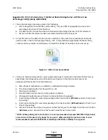
Suggested
O
2
Trim
Commissioning
‐
Traditional
Nozzle
Mixing
Burner
with
No
or
Low
Percentage
FGR
(Typically
LMV52.240)
1.
The
commissioning
procedure
assumes
the
following:
a.
All
Pre
‐
Requisites
for
an
LMV52
system
with
O
2
trim
(and
VSD
if
equipped)
have
been
met
according
to
Section
4
of
this
literature.
b.
The
Ratio
Control
Curves
have
been
commissioned
according
to
Section
4
of
this
literature.
c.
Section
6
of
this
literature
has
been
read
and
understood
up
to
this
point.
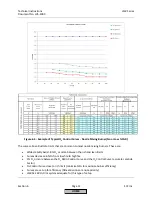
2.
As
was
the
case
for
the
Ratio
Control
Curves
in
Section
4,
the
same
free
spreadsheet
can
also
be
used
to
assist
in
the
commissioning
of
the
O
2
trim.
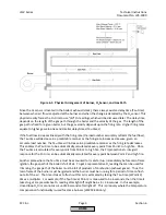
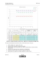
This
spreadsheet
graphically
illustrates
the
O
2
curves
as
well
as
provides
an
orderly
way
to
record
the
details
of
how
the
burner
was
set
up.
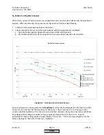
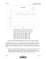
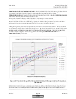
Figure
6
‐
3:
LMVx
Curves
Spreadsheet
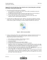
3.
The
key
to
commissioning
the
O
2
curves
quickly
and
easily
is
contained
in
the
Ratio
Control
Curves.
Specifically,
the
following
must
be
achieved
for
each
point
on
the
Ratio
Control
Curves
(as
paraphrased
from
Section
4
of
this
literature):
a.
Safe,
efficient
combustion
as
verified
by
a
calibrated
stack
gas
analyzer
b.
The
%
load
matching
the
fuel
flow
within
+/
‐
3%
c.
Emissions
compliance
d.
Smooth
Ratio
Control
Curves
(no
sharp
peaks
or
valleys)
e.
VSD
speed
should
increase
with
load
in
a
linear
fashion
(if
equipped)
f.
Find
and
record
the
%O
2
wet
corresponding
to
the
fuel
rich
limit
(
O2
Alarm
value)
for
each
point
by
probing.*
g.
Find
and
record
the
%O
2
wet
corresponding
to
the
fuel
lean
limit
(
O2
MaxValue
)
for
Point
1
and
Point
10
by
probing.*
h.
Last
but
not
least,
leave
the
curve
points
so
that
the
%O
2
wet
is
2%
higher
than
the
fuel
rich
limit
(
O2
Alarm
value).
Record
this
as
the
"saved"
value
for
each
curve
point.
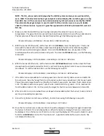
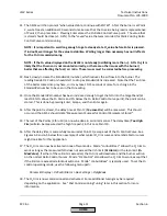
*
NOTE:
When
probing
the
fuel
rich
limit,
it
is
not
recommended
to
exceed
200
PPM
CO
(dry
basis)
or
less
than
1.0%
O
2
(wet
or
dry
basis)
for
any
point.
When
probing
the
fuel
lean
limit,
it
is
not
recommended
to
exceed
200
PPM
CO
or
adversely
affect
flame
stability
for
any
point.
HOME
Summary of Contents for LMV 5 Series
Page 2: ...Intentionally Left Blank ...
Page 41: ...LMV Series Technical Instructions Document No LV5 1000 SCC Inc Page 7 Section 2 HOME ...
Page 42: ...Technical Instructions LMV Series Document No LV5 1000 Section 2 Page 8 SCC Inc HOME ...
Page 43: ...LMV Series Technical Instructions Document No LV5 1000 SCC Inc Page 9 Section 2 HOME ...
Page 44: ...Technical Instructions LMV Series Document No LV5 1000 Section 2 Page 10 SCC Inc HOME ...
Page 45: ...LMV Series Technical Instructions Document No LV5 1000 SCC Inc Page 11 Section 2 HOME ...
Page 46: ...Technical Instructions LMV Series Document No LV5 1000 Section 2 Page 12 SCC Inc HOME ...
Page 47: ...LMV Series Technical Instructions Document No LV5 1000 SCC Inc Page 13 Section 2 HOME ...
Page 48: ...Technical Instructions LMV Series Document No LV5 1000 Section 2 Page 14 SCC Inc HOME ...
Page 49: ...LMV Series Technical Instructions Document No LV5 1000 SCC Inc Page 15 Section 2 HOME ...
Page 50: ...Technical Instructions LMV Series Document No LV5 1000 Section 2 Page 16 SCC Inc HOME ...
Page 51: ...LMV Series Technical Instructions Document No LV5 1000 SCC Inc Page 17 Section 2 HOME ...
Page 52: ...Technical Instructions LMV Series Document No LV5 1000 Section 2 Page 18 SCC Inc HOME ...
Page 53: ...LMV Series Technical Instructions Document No LV5 1000 SCC Inc Page 19 Section 2 HOME ...
Page 54: ...Technical Instructions LMV Series Document No LV5 1000 Section 2 Page 20 SCC Inc HOME ...
Page 55: ...LMV Series Technical Instructions Document No LV5 1000 SCC Inc Page 21 Section 2 HOME ...
Page 373: ...Intentionally Left Blank ...

