Technical
Instructions
LMV
Series
Document
No.
LV5
‐
1000
Section
7
Page
16
SCC
Inc.
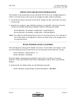
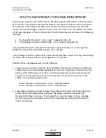
During
O2
Commissioning,
AZL
Says
“
O2
Setpoint
must
lie
0.1%
below
O2
Ratio
Control”
or
“O2
Setpoint
must
lie
0.1%
above
O2
Min”
When
setting
the
O
2
control
curve,
one
of
the
following
messages
appears:
“O2
Setpoint
must
lie
0.1%
below
O2
Ratio
Control
”
“
O2
Setpoint
must
lie
0.1%
above
O2
Min
”.
If
this
is
the
case,
check
the
following:
1.
Ensure
that
there
is
an
absolute
minimum
of
0.2
%O
2
between
the
O
2
alarm
curve
and
the
O
2
ratio
control
curve
at
every
point
on
these
curves.
2.
Also
ensure
that
the
%O
2
that
is
to
be
set
on
the
O
2
control
curve
is
at
least
0.1%
O
2
above
the
O
2
alarm
curve
and
0.1%
O
2
below
the
O
2
ratio
control
curve.
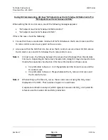
Note
1
:
In
most
cases,
the
%O
2
gap
between
the
curves
should
be
larger
than
the
absolute
minimum.
Depending
on
the
burner
characteristic,
doing
this
may
also
lead
to
more
trouble
‐
free
operation.
See
Section
6
for
more
information
on
these
curves.
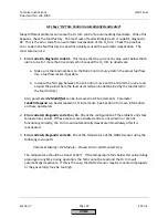
It
is
preferable
to
have
a
1
to
1.5%
gap
between
the
O
2
alarm
curve
and
the
O
2
control
curve.
It
is
preferable
to
have
a
1.5%
gap
between
the
O
2
ratio
control
curve
and
the
O
2
control
curve.
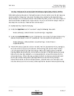
Note
2
:
When
setting
up
the
three
O
2
curves,
these
curves
are
set
using
the
%O
2
values
displayed
on
the
AZL5.
These
values
are
given
on
a
wet
basis.
A
separate
combustion
analyzer
(which
typically
measures
dry
%O
2
)
is
required
for
reference
and
to
monitor
CO
and
NOx
production.
HOME
Summary of Contents for LMV 5 Series
Page 2: ...Intentionally Left Blank ...
Page 41: ...LMV Series Technical Instructions Document No LV5 1000 SCC Inc Page 7 Section 2 HOME ...
Page 42: ...Technical Instructions LMV Series Document No LV5 1000 Section 2 Page 8 SCC Inc HOME ...
Page 43: ...LMV Series Technical Instructions Document No LV5 1000 SCC Inc Page 9 Section 2 HOME ...
Page 44: ...Technical Instructions LMV Series Document No LV5 1000 Section 2 Page 10 SCC Inc HOME ...
Page 45: ...LMV Series Technical Instructions Document No LV5 1000 SCC Inc Page 11 Section 2 HOME ...
Page 46: ...Technical Instructions LMV Series Document No LV5 1000 Section 2 Page 12 SCC Inc HOME ...
Page 47: ...LMV Series Technical Instructions Document No LV5 1000 SCC Inc Page 13 Section 2 HOME ...
Page 48: ...Technical Instructions LMV Series Document No LV5 1000 Section 2 Page 14 SCC Inc HOME ...
Page 49: ...LMV Series Technical Instructions Document No LV5 1000 SCC Inc Page 15 Section 2 HOME ...
Page 50: ...Technical Instructions LMV Series Document No LV5 1000 Section 2 Page 16 SCC Inc HOME ...
Page 51: ...LMV Series Technical Instructions Document No LV5 1000 SCC Inc Page 17 Section 2 HOME ...
Page 52: ...Technical Instructions LMV Series Document No LV5 1000 Section 2 Page 18 SCC Inc HOME ...
Page 53: ...LMV Series Technical Instructions Document No LV5 1000 SCC Inc Page 19 Section 2 HOME ...
Page 54: ...Technical Instructions LMV Series Document No LV5 1000 Section 2 Page 20 SCC Inc HOME ...
Page 55: ...LMV Series Technical Instructions Document No LV5 1000 SCC Inc Page 21 Section 2 HOME ...
Page 373: ...Intentionally Left Blank ...

