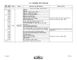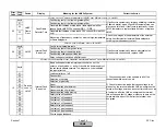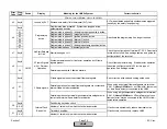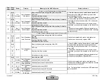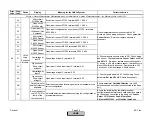
Error
Code
Diag.
Code
Device
Display
Meaning for the LMV5x System
Corrective Action
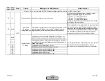
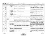
Any #
Code for VSD
Module Fault
Basic unit has detected a fault in connection with the VSD
module
01
Speed Acquisition
faulty
Internal VSD module test was not successful
02
Wrong Direction
of Rotation
Fan rotates in the wrong direction
1) Check to see if the motor’s direction of rotation is
correct. Reverse if necessary
2) Check to see if the arrow on the speed wheel points
in the correct direction of rotation. Reverse if
necessary.
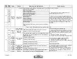
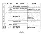
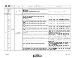
03
Speed Acquisition
faulty
Pulse sequence and length at the speed input were different
from those anticipated
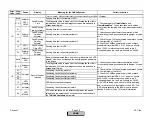
04
Standardization
canceled
because of VSD
Fan was not able to keep the standardized speed at a constant
level
05
Standardization
canceled
because of Air
Actuator
Air actuator (or other air influenced actuator) has not reached
the prepurge position.
For this reason, speed standardization is not possible
1) Check to see if all air-influencing actuators travel to
the prepurge position and remain in that position for the
VSD standardization.
2) Ensure torque requirements of air influencing
dampers / valves is less than actuator output.
3) Verify that no air influencing damper / valve is bound.
4) Check the two 12V fuses located under black covers
on the right side of the LMV5
5) Check the CANBus power supply (blue or black
transformer) terminal SEK2. Pin 1 and pin 4 should
have 12VAC to reference ground which is pin 2.
Voltage between pin 1 and pin 4 should be 24VAC.
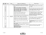
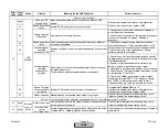
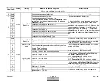
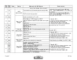
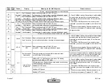
06
Speed Test was
not successfully
completed
Internal VSD module speed test was not successful
Set parameter
Settling Time
to 16.
If fault occurs sporadically, reduce electrical noise.
If fault occurs continuously, replace LMV5.
07
Safety loop open Standardization not possible when safety loop is open
Check all switches wired into the safety loop circuit.
This also includes the burner flange circuit.
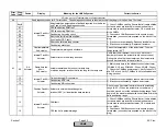
21
Any #
Safety Loop open
Limit switches wired into the safety loop have opened (such as
low low water or high Limit)
Check all switches wired into the safety loop circuit.
This also includes the burner flange circuit.
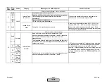
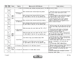
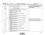
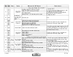
22
Any #
Internal Temp
Limiter
has responded
Internal temperature limiter has switched off because the value
of parameter
TL_Thresh_Off
has been exceeded.
Check the burner / boiler temperature sensor located on
terminal X60.
If fault occurs sporadically, reduce electrical noise.
If fault occurs continuously, replace LMV5.
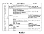
VSD
Module
1) Check and or adjust the gap between the speed
wheel and the sensor. The gap should be about 1/16"
(2mm) or about two turns away from the speed wheel.
2) Check the wiring of the speed sensor. Ensure
reference ground is connected.
1F
Fault with VSD
Devices
conn. to
LMV5
Fault with devices or wiring connected to the Base Unit (LMV5)
Section 7
Page 30
SCC Inc.
HOME
HOME
Summary of Contents for LMV 5 Series
Page 2: ...Intentionally Left Blank ...
Page 41: ...LMV Series Technical Instructions Document No LV5 1000 SCC Inc Page 7 Section 2 HOME ...
Page 42: ...Technical Instructions LMV Series Document No LV5 1000 Section 2 Page 8 SCC Inc HOME ...
Page 43: ...LMV Series Technical Instructions Document No LV5 1000 SCC Inc Page 9 Section 2 HOME ...
Page 44: ...Technical Instructions LMV Series Document No LV5 1000 Section 2 Page 10 SCC Inc HOME ...
Page 45: ...LMV Series Technical Instructions Document No LV5 1000 SCC Inc Page 11 Section 2 HOME ...
Page 46: ...Technical Instructions LMV Series Document No LV5 1000 Section 2 Page 12 SCC Inc HOME ...
Page 47: ...LMV Series Technical Instructions Document No LV5 1000 SCC Inc Page 13 Section 2 HOME ...
Page 48: ...Technical Instructions LMV Series Document No LV5 1000 Section 2 Page 14 SCC Inc HOME ...
Page 49: ...LMV Series Technical Instructions Document No LV5 1000 SCC Inc Page 15 Section 2 HOME ...
Page 50: ...Technical Instructions LMV Series Document No LV5 1000 Section 2 Page 16 SCC Inc HOME ...
Page 51: ...LMV Series Technical Instructions Document No LV5 1000 SCC Inc Page 17 Section 2 HOME ...
Page 52: ...Technical Instructions LMV Series Document No LV5 1000 Section 2 Page 18 SCC Inc HOME ...
Page 53: ...LMV Series Technical Instructions Document No LV5 1000 SCC Inc Page 19 Section 2 HOME ...
Page 54: ...Technical Instructions LMV Series Document No LV5 1000 Section 2 Page 20 SCC Inc HOME ...
Page 55: ...LMV Series Technical Instructions Document No LV5 1000 SCC Inc Page 21 Section 2 HOME ...
Page 373: ...Intentionally Left Blank ...

