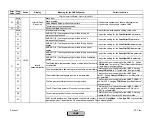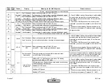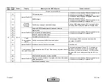
Error
Code
Diag.
Code
Device
Display
Meaning for the LMV5x System
Corrective Action
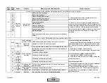
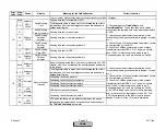
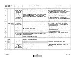
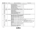
0C
Safety time 2 gas too long
0D
Safety time 2 gas too long
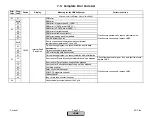
Any #
-
Fault at deactivated inputs
01
Controller input
connected
but deactivated
Controller input (burner on / off switch) connected but
deactivated, terminal X5-03.1
02
Air Press Switch
connected but
deactivated
APS connected but deactivated,
terminal X3-02.1
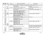
03
FCC / FGR –
APS connected
but deactivated
FCC / FGR – PS connected but deactivated,
terminal X4-01.3
04
Gas Pressure-
MIN connected
but deactivated
Low gas pressure switch connected but deactivated,
terminal X9-03.4
05
Gas Pressure-
MAX connected
but deactivated
High gas pressure switch connected but deactivated,
terminal X9-03.3
06
Oil Pressure min
connected but
deactivated
Low oil pressure switch connected but deactivated,
terminal X5-01.2
07
Oil Pressure max
connected but
deactivated
High oil pressure switch connected but deactivated,
terminal X5-02.2
08
Start Signal Oil
connected but
deactivated
Start release oil connected but deactivated,
terminal X6-01.1
09
HO Start
connected but
deactivated
HO start connected but deactivated,
terminal X6-01.3
0A
Start Signal Gas
connected but
deactivated
Start release gas connected but deactivated,
terminal X7-03.2
0B
HO Start
connected but
deactivated
High-temperature flame safeguard connected but deactivated,
terminal X6-01.3
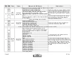
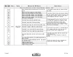
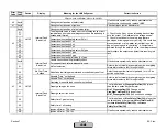
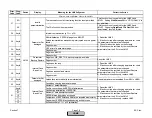
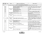
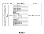
Internal Fault
Basic Unit
43
Fault with devices or wiring connected to the Base Unit (LMV5) / or Base Unit (LMV5)
44
Check inputs according to the diagnostic code.
Disconnect wires or activate inputs for the specific
application. Information concerning the configuration of
the terminals can be found in the settings section.
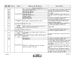
LMV5
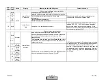
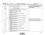
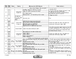
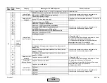
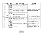
The time defined by
Max SafetyTGas(Oil)
is less than
the time defined by parameter
SafetyTme2Gas(Oil)
.
Increase
Max SafetyTGas(Oil)
or decrease
SafetyTme2Gas(Oil)
.
Section 7
Page 35
SCC Inc.
HOME
HOME
Summary of Contents for LMV 5 Series
Page 2: ...Intentionally Left Blank ...
Page 41: ...LMV Series Technical Instructions Document No LV5 1000 SCC Inc Page 7 Section 2 HOME ...
Page 42: ...Technical Instructions LMV Series Document No LV5 1000 Section 2 Page 8 SCC Inc HOME ...
Page 43: ...LMV Series Technical Instructions Document No LV5 1000 SCC Inc Page 9 Section 2 HOME ...
Page 44: ...Technical Instructions LMV Series Document No LV5 1000 Section 2 Page 10 SCC Inc HOME ...
Page 45: ...LMV Series Technical Instructions Document No LV5 1000 SCC Inc Page 11 Section 2 HOME ...
Page 46: ...Technical Instructions LMV Series Document No LV5 1000 Section 2 Page 12 SCC Inc HOME ...
Page 47: ...LMV Series Technical Instructions Document No LV5 1000 SCC Inc Page 13 Section 2 HOME ...
Page 48: ...Technical Instructions LMV Series Document No LV5 1000 Section 2 Page 14 SCC Inc HOME ...
Page 49: ...LMV Series Technical Instructions Document No LV5 1000 SCC Inc Page 15 Section 2 HOME ...
Page 50: ...Technical Instructions LMV Series Document No LV5 1000 Section 2 Page 16 SCC Inc HOME ...
Page 51: ...LMV Series Technical Instructions Document No LV5 1000 SCC Inc Page 17 Section 2 HOME ...
Page 52: ...Technical Instructions LMV Series Document No LV5 1000 Section 2 Page 18 SCC Inc HOME ...
Page 53: ...LMV Series Technical Instructions Document No LV5 1000 SCC Inc Page 19 Section 2 HOME ...
Page 54: ...Technical Instructions LMV Series Document No LV5 1000 Section 2 Page 20 SCC Inc HOME ...
Page 55: ...LMV Series Technical Instructions Document No LV5 1000 SCC Inc Page 21 Section 2 HOME ...
Page 373: ...Intentionally Left Blank ...

