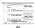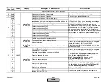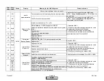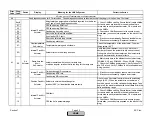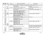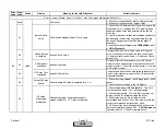
Error
Code
Diag.
Code
Device
Display
Meaning for the LMV5x System
Corrective Action
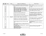
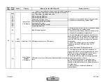
Any #
Basic unit has detected wrong state of the oil actuator
01
CRC error
02
Key error main loop counter
03
No feedback for max. number
Any #
Basic unit has detected wrong state of the auxiliary 1 actuator
01
CRC error
02
Key error main loop counter
03
No feedback for max. number
Any #
Basic unit has detected wrong state of the auxiliary 2 actuator
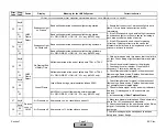
01
CRC error
02
Key error main loop counter
03
No feedback for max. number
Any #
Basic unit has detected wrong state of the internal load
controller
01
CRC error
02
Key error main loop counter
03
No feedback for max. number
Any #
Basic unit has detected wrong state of the AZLI
01
CRC error
02
Key error main loop counter
03
No feedback for max. number
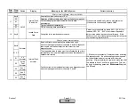
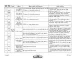
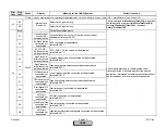
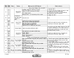
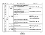
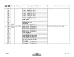
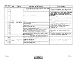
Any #
All
Plausibility fault NMT
01
Actuator
Fault Feedback
Actuator
Undefined fault class of actuator
02
LMV5
Fault Feedback
Load Controller
Undefined fault class of load controller
03
AZL5
Fault Feedback
AZL
Undefined fault class of AZL5
04
VSD
module
Fault Feedback
VSD Module
Undefined fault class of VSD module
05
O2 Mod.
Fault Feedback
O2 Module
Undefined fault class of O2 module
If fault occurs sporadically, reduce electrical noise.
If fault occurs constantly, replace the defective unit (see
diagnostic code) or the LMV5.
Note: The internal load controller and VSD module are
part of the LMV5.
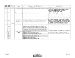
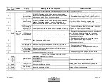
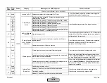
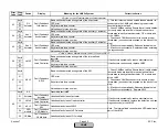
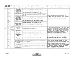
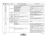
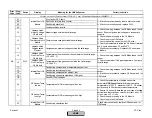
Oil
Actuator
83
84
Aux 2
Actuator
87
Fault with Connected Actuators
85
1) This fault occurs when an un-addressed actuator is
connected to the CANBus. Addressing the actuator
should eliminate the fault.
2) Check CANBus cabling. Ensure that all cable shields
(screens) which are located in the cable sheath are
terminated correctly at each actuator, O2 module, and
at the LMV5x...
3) Check each CANBus connector to ensure proper
termination (no conductors exposed on the back of the
plug)
4) If fault occurs sporadically: Reduce electrical noise.
5) If fault occurs constantly: Replace actuator according
to diagnostic code.
Fault Feedback
Oil Actuator
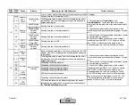
Aux 1
Actuator
Fault Feedback
Aux Actuator 1
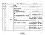
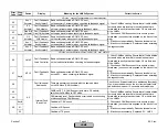
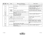
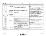
If fault occurs sporadically, reduce electrical noise.
If fault occurs continuously, replace LMV5.
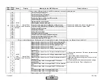
Fault Feedback
AZL5
1) Check CANBus cabling. Ensure that all cable shields
(screens) which are located in the cable sheath are
terminated correctly at each actuator, O2 module, and
at the LMV5
2) Check each CANBus connector to ensure proper
termination (no conductors exposed on the back of the
plug)
3) If fault occurs sporadically: Reduce electrical noise.
4) If fault occurs constantly: Replace AZL5...
Fault Feedback
Aux Actuator 2
Fault with Base Unit (LMV5) or AZL5
LMV5
AZL5
88
Fault Feedback
Load Controller
86
Section 7
Page 40
SCC Inc.
HOME
HOME
Summary of Contents for LMV 5 Series
Page 2: ...Intentionally Left Blank ...
Page 41: ...LMV Series Technical Instructions Document No LV5 1000 SCC Inc Page 7 Section 2 HOME ...
Page 42: ...Technical Instructions LMV Series Document No LV5 1000 Section 2 Page 8 SCC Inc HOME ...
Page 43: ...LMV Series Technical Instructions Document No LV5 1000 SCC Inc Page 9 Section 2 HOME ...
Page 44: ...Technical Instructions LMV Series Document No LV5 1000 Section 2 Page 10 SCC Inc HOME ...
Page 45: ...LMV Series Technical Instructions Document No LV5 1000 SCC Inc Page 11 Section 2 HOME ...
Page 46: ...Technical Instructions LMV Series Document No LV5 1000 Section 2 Page 12 SCC Inc HOME ...
Page 47: ...LMV Series Technical Instructions Document No LV5 1000 SCC Inc Page 13 Section 2 HOME ...
Page 48: ...Technical Instructions LMV Series Document No LV5 1000 Section 2 Page 14 SCC Inc HOME ...
Page 49: ...LMV Series Technical Instructions Document No LV5 1000 SCC Inc Page 15 Section 2 HOME ...
Page 50: ...Technical Instructions LMV Series Document No LV5 1000 Section 2 Page 16 SCC Inc HOME ...
Page 51: ...LMV Series Technical Instructions Document No LV5 1000 SCC Inc Page 17 Section 2 HOME ...
Page 52: ...Technical Instructions LMV Series Document No LV5 1000 Section 2 Page 18 SCC Inc HOME ...
Page 53: ...LMV Series Technical Instructions Document No LV5 1000 SCC Inc Page 19 Section 2 HOME ...
Page 54: ...Technical Instructions LMV Series Document No LV5 1000 Section 2 Page 20 SCC Inc HOME ...
Page 55: ...LMV Series Technical Instructions Document No LV5 1000 SCC Inc Page 21 Section 2 HOME ...
Page 373: ...Intentionally Left Blank ...

