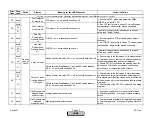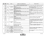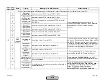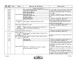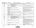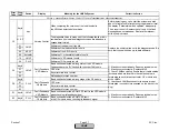
Error
Code
Diag.
Code
Device
Display
Meaning for the LMV5x System
Corrective Action
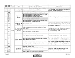
60
Timeout during calibrate_ADC
61
Timeout during read_conversion
62
Timeout during calibrate_ADC
63
Fault during RedInv reading from A/D converter
64
Fault internal A/D converter
65
Gain register has been changed
66
Offset register has been changed
67
Too great / small gain for self-calibration of A/D converter
68
Too great / small offset for self-calibration of A/D converter
69
Fault internal A/D converter
6A
Fault during PWM test
6B
Faulty reference voltage
6C
Fault transmitter power supply
6D
Fault analog output, voltage deviation too great
6E
Fault during resistance test PT100 input (X60)
6F
Fault during diode test PT100 input
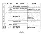
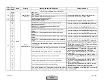
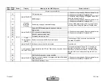
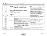
70
Measured value varies too much: PT100 sensor (terminal X60)
71
Measured value varies too much: PT100 line (terminal X60)
72
Measured value varies too much: PT1000 (terminal X60)
73
Measured value varies too much: PWM
74
Measured value varies too much: Voltage measurement input 2
(terminal X61)
75
Measured value varies too much: Current measurement input 2
(terminal X61)
76
Measured value varies too much: Voltage measurement input 3
(terminal X62)
77
Measured value varies too much: Current measurement input 3
(terminal X62)
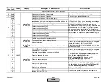
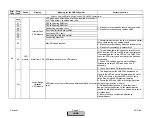
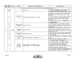
78
Excessive voltage value or wrong polarity PT100 sensor
(terminal X60)
79
Excessive voltage value or wrong polarity PT100 line (terminal
X60)
7A
Excessive voltage value or wrong polarity PT1000 (terminal
X60)
7B
Excessive voltage value or wrong polarity PWM
7C
Excessive voltage value or wrong polarity voltage
measurement input 2 (terminal X61)
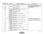
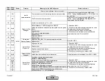
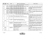
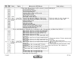
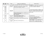
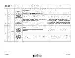
Fault with Base Unit (LMV5) Internal Load Controller
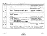
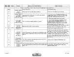
Fault with Sensors Connected to Internal Load Controller, in Base Unit (LMV5)
LMV5
Load
Controller
Module
Internal Fault
Load Controller
If fault occurs sporadically, reduce electrical noise.
If fault occurs continuously, replace LMV5.
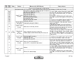
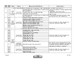
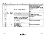
A6
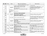
A6
LMV5
Load
Controller
Module
Internal Fault
Load Controller
1) Check wiring and sensor. Re-wire or replace sensors
if necessary.
2) Use shielded cable on sensor wiring.
3) Make sure that sensor wiring is not run next to high
voltage AC wiring.
4) If the diagnostic code indicates excessive voltage,
check input with meter. Trace voltage source.
Section 7
Page 46
SCC Inc.
HOME
HOME
Summary of Contents for LMV 5 Series
Page 2: ...Intentionally Left Blank ...
Page 41: ...LMV Series Technical Instructions Document No LV5 1000 SCC Inc Page 7 Section 2 HOME ...
Page 42: ...Technical Instructions LMV Series Document No LV5 1000 Section 2 Page 8 SCC Inc HOME ...
Page 43: ...LMV Series Technical Instructions Document No LV5 1000 SCC Inc Page 9 Section 2 HOME ...
Page 44: ...Technical Instructions LMV Series Document No LV5 1000 Section 2 Page 10 SCC Inc HOME ...
Page 45: ...LMV Series Technical Instructions Document No LV5 1000 SCC Inc Page 11 Section 2 HOME ...
Page 46: ...Technical Instructions LMV Series Document No LV5 1000 Section 2 Page 12 SCC Inc HOME ...
Page 47: ...LMV Series Technical Instructions Document No LV5 1000 SCC Inc Page 13 Section 2 HOME ...
Page 48: ...Technical Instructions LMV Series Document No LV5 1000 Section 2 Page 14 SCC Inc HOME ...
Page 49: ...LMV Series Technical Instructions Document No LV5 1000 SCC Inc Page 15 Section 2 HOME ...
Page 50: ...Technical Instructions LMV Series Document No LV5 1000 Section 2 Page 16 SCC Inc HOME ...
Page 51: ...LMV Series Technical Instructions Document No LV5 1000 SCC Inc Page 17 Section 2 HOME ...
Page 52: ...Technical Instructions LMV Series Document No LV5 1000 Section 2 Page 18 SCC Inc HOME ...
Page 53: ...LMV Series Technical Instructions Document No LV5 1000 SCC Inc Page 19 Section 2 HOME ...
Page 54: ...Technical Instructions LMV Series Document No LV5 1000 Section 2 Page 20 SCC Inc HOME ...
Page 55: ...LMV Series Technical Instructions Document No LV5 1000 SCC Inc Page 21 Section 2 HOME ...
Page 373: ...Intentionally Left Blank ...

