Technical Instructions
LMV Series
Document No. LV5-1000
Section 1
Page 24
SCC Inc.
1-3: Mounting
LMV5 Controller
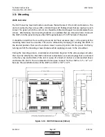
The LMV5 must be mounted inside an enclosure that will protect it from dirt and moisture. The
unit is mounted by four screws (M5 x 0.8mm thread, #2 Phillips drive) that are captive in each
corner. The panel, which the unit sits on, should be drilled and tapped to accommodate these
screws. Alternatively, two mounting brackets are available that use clearance holes to mount
the LMV5 into the panel and space the LMV5 approximate 1.25” off the back of the panel.
It should be noted that the mounting screws do not have excessive play, so the spacing of the
mounting holes must be accurate. This can be achieved by clamping or securing the LMV5 in
the desired position. Then use the captive screws to score (4) circles into the panel. Do this by
turning each of the mounting screws clockwise while applying pressure to the screwdriver.
During the mounting process, consideration should also be given to the various plugs and wires
that must be attached to the LMV5. Electrical connections are made via plugs that are located
in the face, top and bottom of the unit. A space of at least (2) inches is recommended above
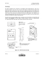
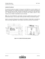
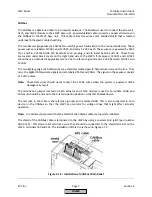
and below the LMV5. The recommended total space to leave for the LMV5 is 12” x 12” x 4”
because the overall dimensions of the LMV5 are 9.84” x 7.87” x 3.25”.
Figure 1-3.1: LMV5 Dimensions (inches)
HOME
Summary of Contents for LMV 5 Series
Page 2: ...Intentionally Left Blank ...
Page 41: ...LMV Series Technical Instructions Document No LV5 1000 SCC Inc Page 7 Section 2 HOME ...
Page 42: ...Technical Instructions LMV Series Document No LV5 1000 Section 2 Page 8 SCC Inc HOME ...
Page 43: ...LMV Series Technical Instructions Document No LV5 1000 SCC Inc Page 9 Section 2 HOME ...
Page 44: ...Technical Instructions LMV Series Document No LV5 1000 Section 2 Page 10 SCC Inc HOME ...
Page 45: ...LMV Series Technical Instructions Document No LV5 1000 SCC Inc Page 11 Section 2 HOME ...
Page 46: ...Technical Instructions LMV Series Document No LV5 1000 Section 2 Page 12 SCC Inc HOME ...
Page 47: ...LMV Series Technical Instructions Document No LV5 1000 SCC Inc Page 13 Section 2 HOME ...
Page 48: ...Technical Instructions LMV Series Document No LV5 1000 Section 2 Page 14 SCC Inc HOME ...
Page 49: ...LMV Series Technical Instructions Document No LV5 1000 SCC Inc Page 15 Section 2 HOME ...
Page 50: ...Technical Instructions LMV Series Document No LV5 1000 Section 2 Page 16 SCC Inc HOME ...
Page 51: ...LMV Series Technical Instructions Document No LV5 1000 SCC Inc Page 17 Section 2 HOME ...
Page 52: ...Technical Instructions LMV Series Document No LV5 1000 Section 2 Page 18 SCC Inc HOME ...
Page 53: ...LMV Series Technical Instructions Document No LV5 1000 SCC Inc Page 19 Section 2 HOME ...
Page 54: ...Technical Instructions LMV Series Document No LV5 1000 Section 2 Page 20 SCC Inc HOME ...
Page 55: ...LMV Series Technical Instructions Document No LV5 1000 SCC Inc Page 21 Section 2 HOME ...
Page 373: ...Intentionally Left Blank ...

