LMV Series
Technical Instructions
Document No. LV5-1000
SCC Inc.
Page 19
Section 8
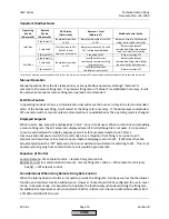
Important Modbus Notes
Operating
Mode
(Address 39)
Remote
Mode
(Address 43)
X62 Action
(Hard-wired)
Remote -> Local
(Address 41)
Modbus Control Action
IntLC Bus
0 (automatic)
Bumpless transition
to W1
Bumpless transition from W3
to W1
Burner controls to W3 setpoint
using internal load controller
1 (manual)
No transition to W1
but W1 is now
displayed as setpoint
Bumpless transition if a valid
W3 is already established
Burner modulates at
commanded firing rate without
load controller intervention
2 (burner off)
Transition to W1
Burner remains off
ExtLC Bus
0 (automatic)
Bumpless transition
to W1
Local/Remote is not
considered, remains at firing
rate in memory
Burner modulates at
commanded firing rate without
load controller intervention*
1 (manual)
2 (burner off)
Local/Remote is not
considered, remains off
Burner remains off
*A value of 1 must be written to address 43 to turn the burner on if a value of 2 was previously written to address 43 to turn the burner off.
Manual Operation
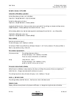
Manual operation from the AZL takes priority over any Modbus operation, although “SetLoad” is
common to the remote firing rate. If a previous firing rate or “SetLoad” is established in memory, it will
be used when manual or remote firing rate operation is commanded.
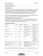
ExtLC Bus Caution
In operating mode ExtLC Bus, a communication loss will cause the burner to stay in the last commanded
state. If the burner was firing, it will restart at the firing rate in memory. If the burner was commanded
off, operation will not resume unless communication is re-established or the operating mode is changed.
Displayed Setpoint
When in ExtLC Bus, setpoint is displayed as “ext LC” since it is not used. When in IntLC Bus and providing
a remote firing rate, the W3 setpoint is displayed (even if it is 0) although it is not used. It is important
to send a valid setpoint for display purposes as well as for bumpless transfer to W1 after a
communication timeout or switch to Local mode since a transition from firing rate control to W3
setpoint control will occur for at least one scan before assigning control to W1. If W3 is less than the
actual setpoint plus the “off” hysteresis, the burner will shut down before transferring to W1. This is not
necessary when going from Local to Remote, but would be good practice.
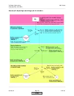
Sequence of Control
Local to Remote: W1 setpoint control -> remote firing rate control
Remote to Local (or communication timeout): remote firing rate control -> W3 setpoint control (very
briefly) -> W1 setpoint control
Considerations When Using Remote Firing Rate Control
When the internal load controller is not used to provide the firing rate, functions such as the thermostat
function and cold start function will not work. However, these should still be configured for use in Local
mode. In Remote mode, it is important to duplicate the functionality when determining the firing rate.
An additional temperature sensor connected to X60 for cold start can be read via Modbus address 83 if
a Pt1000 or Ni1000 RTD is used.
HOME
Summary of Contents for LMV 5 Series
Page 2: ...Intentionally Left Blank ...
Page 41: ...LMV Series Technical Instructions Document No LV5 1000 SCC Inc Page 7 Section 2 HOME ...
Page 42: ...Technical Instructions LMV Series Document No LV5 1000 Section 2 Page 8 SCC Inc HOME ...
Page 43: ...LMV Series Technical Instructions Document No LV5 1000 SCC Inc Page 9 Section 2 HOME ...
Page 44: ...Technical Instructions LMV Series Document No LV5 1000 Section 2 Page 10 SCC Inc HOME ...
Page 45: ...LMV Series Technical Instructions Document No LV5 1000 SCC Inc Page 11 Section 2 HOME ...
Page 46: ...Technical Instructions LMV Series Document No LV5 1000 Section 2 Page 12 SCC Inc HOME ...
Page 47: ...LMV Series Technical Instructions Document No LV5 1000 SCC Inc Page 13 Section 2 HOME ...
Page 48: ...Technical Instructions LMV Series Document No LV5 1000 Section 2 Page 14 SCC Inc HOME ...
Page 49: ...LMV Series Technical Instructions Document No LV5 1000 SCC Inc Page 15 Section 2 HOME ...
Page 50: ...Technical Instructions LMV Series Document No LV5 1000 Section 2 Page 16 SCC Inc HOME ...
Page 51: ...LMV Series Technical Instructions Document No LV5 1000 SCC Inc Page 17 Section 2 HOME ...
Page 52: ...Technical Instructions LMV Series Document No LV5 1000 Section 2 Page 18 SCC Inc HOME ...
Page 53: ...LMV Series Technical Instructions Document No LV5 1000 SCC Inc Page 19 Section 2 HOME ...
Page 54: ...Technical Instructions LMV Series Document No LV5 1000 Section 2 Page 20 SCC Inc HOME ...
Page 55: ...LMV Series Technical Instructions Document No LV5 1000 SCC Inc Page 21 Section 2 HOME ...
Page 373: ...Intentionally Left Blank ...

