LMV Series
Technical Instructions
Document No. LV5-1000
SCC Inc.
Page 5
Section 2
Load Controller
The LMV51.1 and all LMV52 are equipped with a load controller. The load controller is very flexible and
can read multiple sensors simultaneously. Typically, either a temperature sensor or pressure sensor is
connected for burner modulation. Both a pressure and a temperature sensor can be used in
conjunction for certain applications such as cold start (thermal shock protection).
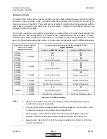
The load controller has six different operational modes that can be changed by opening or closing a
connection on X62. These six different modes of operation are outlined in Section 4. By using a dry
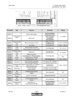
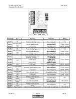
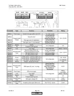
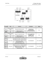
contact, or switch, between terminals X62.1 and X62.2, the mode and / or setpoint of the internal load
controller can be changed.
If the load controller is in “IntLC” (internal load controller), setpoint W1 will be used if X62.1 / X62.2 is
open and setpoint W2 will be used if X62.1 / X62.2 is closed. If the load controller is in any other mode
and X62.1 / X62.2 is closed, the LMV5 will revert back to “IntLC” and will use setpoint W1. See Section 4
for more information about load controller modes.
This feature is commonly used when switching the LMV5 from “ExtLC X62” (remote modulation via a 4-
20mA source wired into terminals X62.3 and X62.4) back to “IntLC” (local, using LMV5 load controller for
modulation of the burner).
The load controller also provides power for 4-20 mA or 0-10 VDC sensors, or 4-20 mA or 0-10 VDC
externally powered sensors. The wiring of these sensors is covered in Section 2-3.
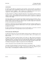
Floating / Bumping and Multistage Oil
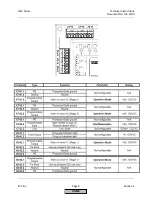
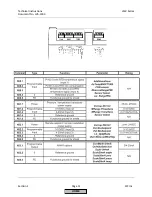
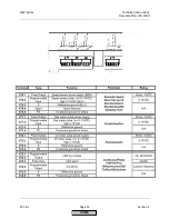
Terminals X5-03.2 and X5-03.3 can be used for floating / bumping control or multistage oil control, also
called 3-position control. This option can be done on all models of LMV5, and is required on the
LMV51.0 models.
Through the use of floating / bumping, the LMV5 can be driven to a higher firing rate by placing line
voltage on terminal X5-03.2 and to a lower firing rate by removing line voltage from X5-03.2 and placing
line voltage on X5-03.3. No voltage on X5-03.2 or X5-03.3 keeps the current firing rate. By alternating
voltage on these terminals, the firing rate of the LMV5 can be increased, decreased, or kept the same.
The floating / bumping type of modulation is typically done with an RWF40/50/55.
A relay can be placed in the line connected to X5-03.2 if a low fire hold is desired.
If externally controlled multistage oil is selected, terminal X5-03.1 is energized for stage 1. Terminal X5-
03.2 can be energized to put the burner in stage 2, and terminal X5-03.3 can be energized to put the
burner in stage 3. De-energizing these terminals takes the burner out of stage 2 or 3.
HOME
Summary of Contents for LMV 5 Series
Page 2: ...Intentionally Left Blank ...
Page 41: ...LMV Series Technical Instructions Document No LV5 1000 SCC Inc Page 7 Section 2 HOME ...
Page 42: ...Technical Instructions LMV Series Document No LV5 1000 Section 2 Page 8 SCC Inc HOME ...
Page 43: ...LMV Series Technical Instructions Document No LV5 1000 SCC Inc Page 9 Section 2 HOME ...
Page 44: ...Technical Instructions LMV Series Document No LV5 1000 Section 2 Page 10 SCC Inc HOME ...
Page 45: ...LMV Series Technical Instructions Document No LV5 1000 SCC Inc Page 11 Section 2 HOME ...
Page 46: ...Technical Instructions LMV Series Document No LV5 1000 Section 2 Page 12 SCC Inc HOME ...
Page 47: ...LMV Series Technical Instructions Document No LV5 1000 SCC Inc Page 13 Section 2 HOME ...
Page 48: ...Technical Instructions LMV Series Document No LV5 1000 Section 2 Page 14 SCC Inc HOME ...
Page 49: ...LMV Series Technical Instructions Document No LV5 1000 SCC Inc Page 15 Section 2 HOME ...
Page 50: ...Technical Instructions LMV Series Document No LV5 1000 Section 2 Page 16 SCC Inc HOME ...
Page 51: ...LMV Series Technical Instructions Document No LV5 1000 SCC Inc Page 17 Section 2 HOME ...
Page 52: ...Technical Instructions LMV Series Document No LV5 1000 Section 2 Page 18 SCC Inc HOME ...
Page 53: ...LMV Series Technical Instructions Document No LV5 1000 SCC Inc Page 19 Section 2 HOME ...
Page 54: ...Technical Instructions LMV Series Document No LV5 1000 Section 2 Page 20 SCC Inc HOME ...
Page 55: ...LMV Series Technical Instructions Document No LV5 1000 SCC Inc Page 21 Section 2 HOME ...
Page 373: ...Intentionally Left Blank ...


