LMV Series
Technical Instructions
LV5-1000
Menu Path
Parameter
Default
Range
Description
51.1
52.2
52.4
LEGEND -
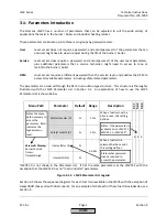
Password Access:
(U)=User, (S)=Service, (O)=OEM, Shaded = Commonly Used, ** = Must Set, X = Has Function, / = Partial Function
LMV
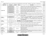
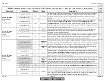
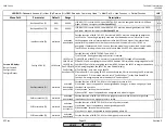
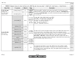
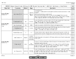
PostpurgeLockout (S)
120s
0.2s-63min
If a lockout condition occurs, and the combustion air fan was running, it will continue
running in the lockout phase (phase 00) for this period of time. This time replaces the
postpurge time in the event of a lockout. If the combustion air fan was not running, the fan
will remain off for the rest of the lockout phase.
MaxTmeStartRel (S)
120s
0.2s-63min
When the LMV5 gets a call for heat, this is the maximum time the LMV5 will hold in phase 21
waiting for a start release. If this time expires and the start release is not made, the LMV5
will go into alarm.
See:
Params & Display > BurnerControl > Times >TimesStartup1 > MinTmeStartRel
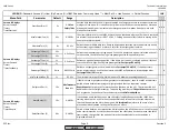
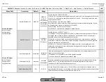
AlarmStartPrev (S)
deact
activated
deactivated
Determines if the alarm OUTPUT X3-01.2 will be energized in the event of a start prevention
(an alarm in standby - Phase 12).
AlarmDelay
sets how long the LMV5 will wait before going
into alarm.
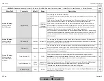
Standby Error (S)
deact
activated
deactivated
If this is set to activated, an alarm will occur if the safety loop is opened in phase 12
(standby). If deactivated, the safety loop can be open when in phase 12 without alarm.
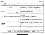
NormDirectStart (S)
Normal
Start
NormalStart
DirectStart
Enables the LMV5 to skip postpurge (T3) time, and go directly into prepurge if there is a call
for heat during postpurge T1. If set to DirectStart, a 3-way valve on OUTPUT X4-03.3 must be
used to check the air pressure switch.
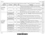
OilPumpCoupling (S)
Magnet-
coupl
Magnetcoupl
Directcoupl
Combined with IgnOilPumpStart determines the behavior of OUTPUT X6-02.3:
1) Magnetcoupl - the output will energize, in either phase 22 or 38, depending on the setting
of
IgnOilPumpStart
. Output will de-energize as soon as main oil valves close.
2) Directcoupl - the output will energize at the same time as the blower, and de-energizes 15
seconds after the blower.
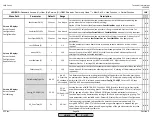
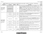
IgnOilPumpStart (S)
on in Ph22
on in Ph22
on in Ph38
If
Magnetcoupl
is selected above, this determines when OUTPUT X6-02.3 is energized. If a
direct spark oil train is selected, spark will occur during prepurge if set to Ph22.
ForcedIntermit (S)
activated
activated
deactivated
When activated, this setting forces the LMV5 to shut the burner down, every 23 hours 50
minutes. The burner will automatically restart. The purpose of this is to check and cycle
safety devices. If a non-self check flame scanner is used, this must be activated.
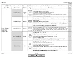
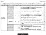
Skip PrepurgeGas (S)
deact
If activated, prepurge for gas will be skipped. Not recommended for most burners.
Skip PrepurgeOil (O)
deact
If activated, prepurge for oil will be skipped. Not recommended for most burners.
Params & Display
>
BurnerControl>
Times>
TimesGeneral
Params & Display>
BurnerControl>
Configuration>
ConfigGeneral
activated
deactivated
x
x x x
x x
SCC Inc.
Page 10
Section 3
HOME
HOME
P - LIST
Summary of Contents for LMV 5 Series
Page 2: ...Intentionally Left Blank ...
Page 41: ...LMV Series Technical Instructions Document No LV5 1000 SCC Inc Page 7 Section 2 HOME ...
Page 42: ...Technical Instructions LMV Series Document No LV5 1000 Section 2 Page 8 SCC Inc HOME ...
Page 43: ...LMV Series Technical Instructions Document No LV5 1000 SCC Inc Page 9 Section 2 HOME ...
Page 44: ...Technical Instructions LMV Series Document No LV5 1000 Section 2 Page 10 SCC Inc HOME ...
Page 45: ...LMV Series Technical Instructions Document No LV5 1000 SCC Inc Page 11 Section 2 HOME ...
Page 46: ...Technical Instructions LMV Series Document No LV5 1000 Section 2 Page 12 SCC Inc HOME ...
Page 47: ...LMV Series Technical Instructions Document No LV5 1000 SCC Inc Page 13 Section 2 HOME ...
Page 48: ...Technical Instructions LMV Series Document No LV5 1000 Section 2 Page 14 SCC Inc HOME ...
Page 49: ...LMV Series Technical Instructions Document No LV5 1000 SCC Inc Page 15 Section 2 HOME ...
Page 50: ...Technical Instructions LMV Series Document No LV5 1000 Section 2 Page 16 SCC Inc HOME ...
Page 51: ...LMV Series Technical Instructions Document No LV5 1000 SCC Inc Page 17 Section 2 HOME ...
Page 52: ...Technical Instructions LMV Series Document No LV5 1000 Section 2 Page 18 SCC Inc HOME ...
Page 53: ...LMV Series Technical Instructions Document No LV5 1000 SCC Inc Page 19 Section 2 HOME ...
Page 54: ...Technical Instructions LMV Series Document No LV5 1000 Section 2 Page 20 SCC Inc HOME ...
Page 55: ...LMV Series Technical Instructions Document No LV5 1000 SCC Inc Page 21 Section 2 HOME ...
Page 373: ...Intentionally Left Blank ...

