LMV Series
Technical Instructions
LV5-1000
Menu Path
Parameter
Default
Range
Description
51.1
52.2
52.4
LEGEND -
Password Access:
(U)=User, (S)=Service, (O)=OEM, Shaded = Commonly Used, ** = Must Set, X = Has Function, / = Partial Function
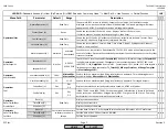
LMV
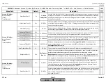
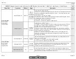
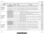
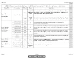
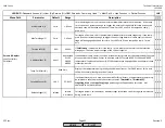
IgnitionPosGas or
IgnitionPosOil (S)
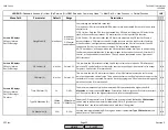
Resets the ignition position of the fuel actuator(s) to an invalid value.
x x x
IgnitionPosAir (S)
Resets the ignition position of the air actuator to an invalid value.
x x x
IgnitionPosAux1 (S)
Resets the ignition position of the aux1 actuator to an invalid value.
x x x
IgnitionPosAux2 (S)
Resets the ignition position of the aux2 actuator to an invalid value.
x x
IgnitionPosAux3 (S)
Resets the ignition position of the aux3 actuator to an invalid value.
x x
IgnitionPosVSD (S)
Resets the ignition speed of the VSD to an invalid value.
x x
Params & Display>
RatioControl>
GasSettings>
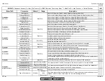
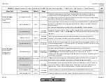
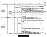
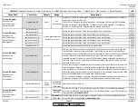
CurveParams (S)**
Not Set
x x x
Curve Settings (S)
Not Set
x x x
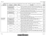
Operation Mode (O)
Mod-
ulating
Modulating
Two-stage
Three-stage
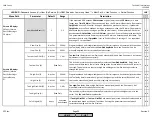
Operation mode for firing oil.
x x x
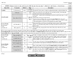
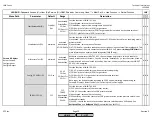
MinLoadGas(Oil) (S)
0%
0-
MaxLoad
Gas(Oil)
Sets the low fire load. During normal operation, the burner will not modulate below this
point. Set to reflect low fire fuel input. For a 10:1 turndown burner, set at 10%. Maximum
setting limited by
MaxLoadGas(Oil)
.
x x x
MaxLoadGas(Oil) (S)
100%
MinLoadGas
(Oil)
-100%
Sets the high fire load. During normal operation, the burner will not modulate above this
point. Minimum setting limited by
MinLoadGas(Oil)
.
x x x
Params & Display>
RatioControl>
Gas/Oil Settings>
SpecialPositions
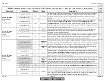
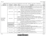
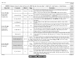
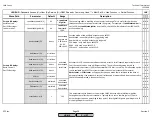
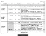
ProgramStop (S)
Params & Display>
RatioControl>
Gas/Oil Settings>
LoadLimits
Params & Display>
RatioControl>
OilSettings>
CurveParams
Go into parameter then
press Enter to reset
Params & Display>
RatioControl>
Gas/Oil Settings>
SpecialPositions>
ResetlgnitPos
deact
See
Description
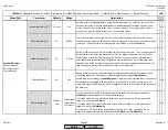
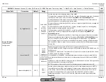
For gas or oil firing, this parameter will stop the sequence in the selected phase. Useful for
commissioning and service work.
The LMV5 can be held in the following phases: 24 Prepurge, 32 Prepurge FGR, 36 Ignition
Position, 44 Interval 1 (pilot stabilize), 52 Interval 2 (main flame stabilize), 72 Postpurge
Position, 76 Postpurge FGR. Program Stop can also be deactivated.
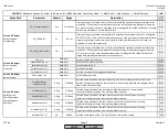
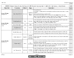
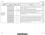
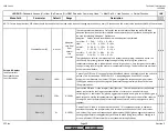
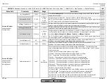
This is where actuator position curves and VSD speed curves are set from low to high fire.
These position curves determine the fuel-air ratio for the burner across the firing range.
Fifteen points can be set from low to high fire. Typically ten points are set. Colons(:) indicate
that the actuator is at the indicated position, (>) indicates the actuator is seeking the
indicated position, (#) indicates the aux 3 FGR actuator is being held at position due to an
FGR hold. If an O2 sensor is attached and activated (LMV52), the wet O2 value will also be
displayed on the screen.
When a specific point is selected (point 2 for example), the LMV5 will prompt if the point is
to be 'changed' or 'deleted'. If 'change' is selected, then the LMV5 will prompt the user to
select 'followed' or 'not followed'. If 'followed' is selected, the LMV5 will drive the actuators /
VSD to the point, and then the point can be changed. If 'not followed' is selected, the LMV5
will not drive to the point, but the point can still be changed.
NOTE : When 'not followed' is selected, the effect of actuator changes cannot be seen on a
combustion analyzer. If 'not followed' is selected, extreme caution must be used.
Points 1-15
x x x
SCC Inc.
Page 19
Section 3
HOME
HOME
P - LIST
Summary of Contents for LMV 5 Series
Page 2: ...Intentionally Left Blank ...
Page 41: ...LMV Series Technical Instructions Document No LV5 1000 SCC Inc Page 7 Section 2 HOME ...
Page 42: ...Technical Instructions LMV Series Document No LV5 1000 Section 2 Page 8 SCC Inc HOME ...
Page 43: ...LMV Series Technical Instructions Document No LV5 1000 SCC Inc Page 9 Section 2 HOME ...
Page 44: ...Technical Instructions LMV Series Document No LV5 1000 Section 2 Page 10 SCC Inc HOME ...
Page 45: ...LMV Series Technical Instructions Document No LV5 1000 SCC Inc Page 11 Section 2 HOME ...
Page 46: ...Technical Instructions LMV Series Document No LV5 1000 Section 2 Page 12 SCC Inc HOME ...
Page 47: ...LMV Series Technical Instructions Document No LV5 1000 SCC Inc Page 13 Section 2 HOME ...
Page 48: ...Technical Instructions LMV Series Document No LV5 1000 Section 2 Page 14 SCC Inc HOME ...
Page 49: ...LMV Series Technical Instructions Document No LV5 1000 SCC Inc Page 15 Section 2 HOME ...
Page 50: ...Technical Instructions LMV Series Document No LV5 1000 Section 2 Page 16 SCC Inc HOME ...
Page 51: ...LMV Series Technical Instructions Document No LV5 1000 SCC Inc Page 17 Section 2 HOME ...
Page 52: ...Technical Instructions LMV Series Document No LV5 1000 Section 2 Page 18 SCC Inc HOME ...
Page 53: ...LMV Series Technical Instructions Document No LV5 1000 SCC Inc Page 19 Section 2 HOME ...
Page 54: ...Technical Instructions LMV Series Document No LV5 1000 Section 2 Page 20 SCC Inc HOME ...
Page 55: ...LMV Series Technical Instructions Document No LV5 1000 SCC Inc Page 21 Section 2 HOME ...
Page 373: ...Intentionally Left Blank ...

