LMV Series
Technical Instructions
LV5-1000
Menu Path
Parameter
Default
Range
Description
51.1
52.2
52.4
LEGEND -
Password Access:
(U)=User, (S)=Service, (O)=OEM, Shaded = Commonly Used, ** = Must Set, X = Has Function, / = Partial Function
LMV
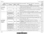
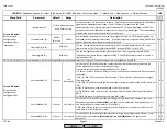
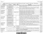
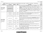
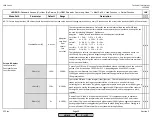
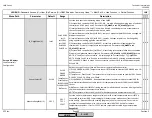
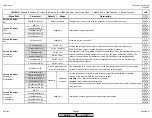
O2TrimBehavior (O)
ForcdAir-
Add
ForcdAirAdd
ForcdAirRed
symmetric
Sets the behavior of the O2 trim when active (not locked). This setting only applies if
StartMode
is set to standard. Three possibilities exist:
1) ForcedAirAdd - O2 trim will add air faster than it will subtract air. Used when the O2
setpoint is close to the
O2 Alarm
.
2) ForcedAirRed - O2 trim will subtract air faster than it will add air. Used when the O2
setpoint is close to
O2 MaxValue
.
3) Symmetric - O2 trim will add and subtract air at the same rate. Used when the O2
setpoint is approximately midway between the
O2 Alarm
and
O2 MaxValue
.
x x
x x
x x
x x
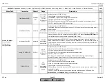
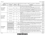
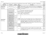
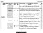
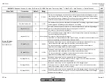
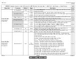
During a load change, this offset temporarily increases the air related load (opens the air
influenced actuators). The amount of load change that will trigger
O2ModOffset
is
determined by the setting of
LoadCtrlSuspend
. How much the air related load is increased is
determined by the setting of this parameter. A setting of 1% should translate into a 1%
increase in measured %O2 during a load change. After active trim is resumed, the offset will
be dissolved.
O2ModOffset (S)
0-5%
0-25%
LowfireAdaptPtNo (S)**
O2 CtrlThreshold (S)
2-15
0%
0%
0-100%
5%
x x
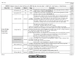
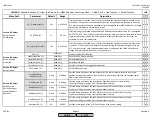
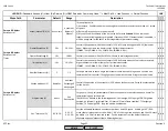
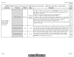
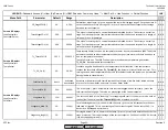
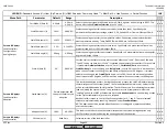
Sets the point that
Tau Low-Fire
is automatically measured. Tau and PI for low fire will be
based on this point. A low fire adapt point must be defined before setting up the O2 trim
curves. Typically the low fire adapt point is chosen at point 2, but a higher point may be
necessary on high-turndown burners and / or oversized stacks.
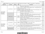
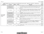
This is the minimum load for the O2 trim. If the load drops below this value, the O2 trim
automatically de-activates. 5% above this load setting the O2 trim control will automatically
reactivate. Typically set to the same load value as the load at LowfireAdaptPtNo.
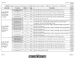
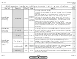
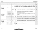
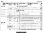
During a load change, the O2 trim will lock and will not actively trim. This is necessary due to
delay time thru the boiler and also different O2 trim setpoints from low fire to high fire.
When locked and not actively trimming, the O2 trim runs on precontrol, meaning that it
calculates where to position the air influenced actuators based on burner characteristics
learned by the LMV5 during O2 commissioning. This parameter determines how much of a
load change will lock the O2 trim and cause it to run on precontrol.
Not Set
Params & Display>
O2Contr/Alarm>
Gas/Oil Settings>
Control Param
LoadCtrlSuspend (S)
SCC Inc.
Page 24
Section 3
HOME
HOME
P - LIST
Summary of Contents for LMV 5 Series
Page 2: ...Intentionally Left Blank ...
Page 41: ...LMV Series Technical Instructions Document No LV5 1000 SCC Inc Page 7 Section 2 HOME ...
Page 42: ...Technical Instructions LMV Series Document No LV5 1000 Section 2 Page 8 SCC Inc HOME ...
Page 43: ...LMV Series Technical Instructions Document No LV5 1000 SCC Inc Page 9 Section 2 HOME ...
Page 44: ...Technical Instructions LMV Series Document No LV5 1000 Section 2 Page 10 SCC Inc HOME ...
Page 45: ...LMV Series Technical Instructions Document No LV5 1000 SCC Inc Page 11 Section 2 HOME ...
Page 46: ...Technical Instructions LMV Series Document No LV5 1000 Section 2 Page 12 SCC Inc HOME ...
Page 47: ...LMV Series Technical Instructions Document No LV5 1000 SCC Inc Page 13 Section 2 HOME ...
Page 48: ...Technical Instructions LMV Series Document No LV5 1000 Section 2 Page 14 SCC Inc HOME ...
Page 49: ...LMV Series Technical Instructions Document No LV5 1000 SCC Inc Page 15 Section 2 HOME ...
Page 50: ...Technical Instructions LMV Series Document No LV5 1000 Section 2 Page 16 SCC Inc HOME ...
Page 51: ...LMV Series Technical Instructions Document No LV5 1000 SCC Inc Page 17 Section 2 HOME ...
Page 52: ...Technical Instructions LMV Series Document No LV5 1000 Section 2 Page 18 SCC Inc HOME ...
Page 53: ...LMV Series Technical Instructions Document No LV5 1000 SCC Inc Page 19 Section 2 HOME ...
Page 54: ...Technical Instructions LMV Series Document No LV5 1000 Section 2 Page 20 SCC Inc HOME ...
Page 55: ...LMV Series Technical Instructions Document No LV5 1000 SCC Inc Page 21 Section 2 HOME ...
Page 373: ...Intentionally Left Blank ...

