LMV Series
Technical Instructions
LV5-1000
Menu Path
Parameter
Default
Range
Description
51.1
52.2
52.4
LEGEND -
Password Access:
(U)=User, (S)=Service, (O)=OEM, Shaded = Commonly Used, ** = Must Set, X = Has Function, / = Partial Function
LMV
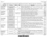
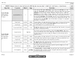
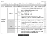
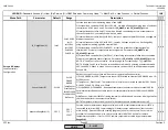
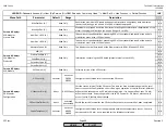
StandardParam (U)
Not Set
Adaption
very slow
slow
normal
fast
very fast
These are preset combinations of values for the for the internal load controller PID loop.
Adaption (autotune) is not performed with this parameter, but values found by adaption can
be used by selecting 'Adaption'. Options are:
Adaption: Values set and recorded here when adaption is performed
very slow: P = 3.4 % I = 273 s D = 48 s
slow: P = 4.7 % I = 250 s D = 44 s
normal: P = 6.4 % I = 136 s D = 24 s
fast: P = 14.5 % I = 77 s D = 14 s
very fast: P = 42.5 % I = 68 s D = 12 s
default: P = 14.5 % I = 120 s D = 0 s
The labels above refer to the response of the system (boiler, piping, loads) and not to the
LMV5 itself. Very slow gives the largest change in firing rate for a given pressure /
temperature change and is typically used on very large systems. Very fast gives the smallest
change in firing rate for a given pressure / temperature change. The default values work well
with most steam boilers.
x x x
P-Part (U)
14.5%
2-500%
P part of the PID loop. P is a type of proportional band around the setpoint, and the units are
percent. This % is based on 14.5 PSIG or 212 F, depending upon if the LMV5 is set for
pressure or temperature. Low values (2%) give an aggressive response and higher values
(100%) give a weak response. Setting this parameter too aggressively will cause the load
(firing rate) to hunt.
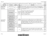
x x x
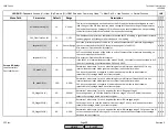
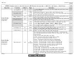
I-Part (U)
120s
0-2000s
I part of the PID loop. I is the integral (reset) function. This component serves to eliminate
steady state error by looking at the accumulation of error over a period of time and
correcting for it. Low values (1s) give an aggressive response and higher values (1000s) give a
weak response. Setting this parameter too aggressively will cause overshoot of the setpoint.
Setting to 0 is not recommended for most applications since P and I are designed to work
together.
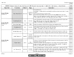
x x x
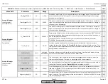
D-Part (U)
0s
0-1000s
D part of the PID loop. D is the derivative function. This component serves to eliminate
overshoot caused by the integral value, and also dampen the action of the P and I values.
Low values (1s) give a weak response and higher values (1000s) give an aggressive response.
Setting this parameter too aggressively will cause the load (firing rate) to hunt. Setting to 0
or to small values (10) works well for many steam boiler applications.
x x x
Params & Display>
LoadController>
ControllerParam>
ContrlParamList
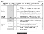
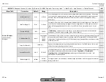
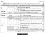
NOTE: For most applications, PID values should be tuned so that the load value does not change more than once every 10 seconds and the actual value trends within 5% of the setpoint.
SCC Inc.
Page 29
Section 3
HOME
HOME
P - LIST
Summary of Contents for LMV 5 Series
Page 2: ...Intentionally Left Blank ...
Page 41: ...LMV Series Technical Instructions Document No LV5 1000 SCC Inc Page 7 Section 2 HOME ...
Page 42: ...Technical Instructions LMV Series Document No LV5 1000 Section 2 Page 8 SCC Inc HOME ...
Page 43: ...LMV Series Technical Instructions Document No LV5 1000 SCC Inc Page 9 Section 2 HOME ...
Page 44: ...Technical Instructions LMV Series Document No LV5 1000 Section 2 Page 10 SCC Inc HOME ...
Page 45: ...LMV Series Technical Instructions Document No LV5 1000 SCC Inc Page 11 Section 2 HOME ...
Page 46: ...Technical Instructions LMV Series Document No LV5 1000 Section 2 Page 12 SCC Inc HOME ...
Page 47: ...LMV Series Technical Instructions Document No LV5 1000 SCC Inc Page 13 Section 2 HOME ...
Page 48: ...Technical Instructions LMV Series Document No LV5 1000 Section 2 Page 14 SCC Inc HOME ...
Page 49: ...LMV Series Technical Instructions Document No LV5 1000 SCC Inc Page 15 Section 2 HOME ...
Page 50: ...Technical Instructions LMV Series Document No LV5 1000 Section 2 Page 16 SCC Inc HOME ...
Page 51: ...LMV Series Technical Instructions Document No LV5 1000 SCC Inc Page 17 Section 2 HOME ...
Page 52: ...Technical Instructions LMV Series Document No LV5 1000 Section 2 Page 18 SCC Inc HOME ...
Page 53: ...LMV Series Technical Instructions Document No LV5 1000 SCC Inc Page 19 Section 2 HOME ...
Page 54: ...Technical Instructions LMV Series Document No LV5 1000 Section 2 Page 20 SCC Inc HOME ...
Page 55: ...LMV Series Technical Instructions Document No LV5 1000 SCC Inc Page 21 Section 2 HOME ...
Page 373: ...Intentionally Left Blank ...

