LMV Series
Technical Instructions
LV5-1000
Menu Path
Parameter
Default
Range
Description
51.1
52.2
52.4
LEGEND -
Password Access:
(U)=User, (S)=Service, (O)=OEM, Shaded = Commonly Used, ** = Must Set, X = Has Function, / = Partial Function
LMV
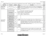
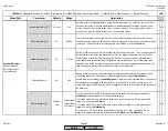
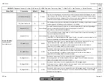
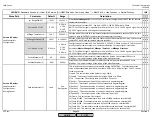
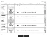
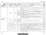
var. RangePtNi (S)
1562 F
32-1562 F
When
MeasureRangePtNi
is set to 1562F, this scales the high end of INPUT X62 for remote
temperature setpoints.
x x x
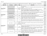
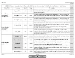
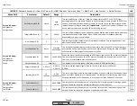
Ext Inp X61 U/I (S)
0..10 V
4..20 mA
2..10 V
0..10 V
0..20 mA
Configuration of terminal X61. Can be 0-10VDC, 2-10VDC, 0-20mA or 4-20mA.
NOTE : For 4-20mA signals, signal limits are 3mA to 21mA. For 0-10 VDC signals, signal limit is
10.5 VDC. Signals not in this range will cause an alarm.
x x x
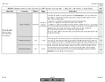
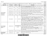
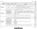
MRange TempSens (S)
194 F
32-3632 F
Sets the end of the scale for a temperature transducer connected to terminal X61. Also, this
serves to scale INPUT X62 if used for remote temperature setpoints.
x x x
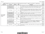
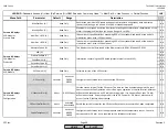
MRange PressSens (S)
29 PSI
0-1449 PSI
Sets the end of the scale for a pressure sensor connected to terminal X61. Also, this serves to
scale INPUT X62 if used for remote pressure setpoints.
x x x
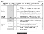
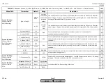
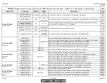
Ext Inp X62 U/I (S)
4..20 mA
4..20 mA
2..10 V
0..10 V
0..20 mA
Configuration of terminal X62. Can be 0-10VDC, 2-10VDC, 0-20mA or 4-20mA. This terminal is
usually used for remote setpoint or remote modulation. This input signal is scaled by
parameter
MeasureRangePtNi
,
MRange TempSens
or
MRange PressSens
.
NOTE : For 4-20mA signals, signal limits are 3mA to 21mA. For 0-10 VDC signals, signal limit is
10.5 VDC. Signals not in this range will cause an alarm.
x x x
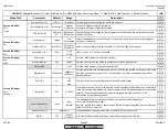
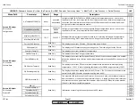
Ext MinSetpoint (S)
0%
0-100%
Establishes the minimum external setpoint that can be input via terminals X62 or via
Modbus. This is a percentage of the range of the attached sensor.
x x x
Ext MaxSetpoint (S)
60%
0-100%
Establishes the maximum external setpoint that can be input via terminals X62 or via
Modbus. This is a percentage of the range of the attached sensor.
x x x
Params & Display>
LoadController>
Configuration>
Analog Output
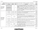
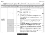
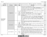
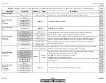
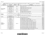
OutValuSelection (S)
Load
See
Description
This selects the process value associated with analog OUTPUT X63. The selected process
value will be transmitted from X63 with either a 0-20mA or a 4-20mA signal. The 15 choices
for this output are:
1) Load - The current load of the burner using 4-20mA.
2) Load 0 - The current load of the burner using 4-20mA or 0-20mA.
3) O2 - The percent O2 currently read by the stack O2 sensor.
4) Pos Air - The current position of the air actuator in angular degrees.
5) Pos Fuel - The current position of the fuel actuator in angular degrees.
6) Pos Aux1 - The current position of the Aux 1 actuator in angular degrees.
7) Pos Aux2 - The current position of the Aux 2 actuator in angular degrees.
8) Pos Aux3 - The current position of the Aux 3 actuator in angular degrees.
9) Speed VSD - The current speed of the VSD motor in percent.
10) Flame - The current raw flame signal.
11) Temp Pt1000 - The temperature read by the Pt1000 sensor on terminal X60.
12) Temp Ni1000 - The temperature read by the Ni1000 sensor on terminal X60.
13) Temp Pt100 - The temperature read by the Pt100 sensor on terminal X60.
14) Temp X61 - The temperature read by the temperature transducer on terminal X61.
15) Press X61 - The pressure read by the pressure transducer on terminal X61.
x x x
Params & Display>
LoadController>
Configuration
SCC Inc.
Page 34
Section 3
HOME
HOME
P - LIST
Summary of Contents for LMV 5 Series
Page 2: ...Intentionally Left Blank ...
Page 41: ...LMV Series Technical Instructions Document No LV5 1000 SCC Inc Page 7 Section 2 HOME ...
Page 42: ...Technical Instructions LMV Series Document No LV5 1000 Section 2 Page 8 SCC Inc HOME ...
Page 43: ...LMV Series Technical Instructions Document No LV5 1000 SCC Inc Page 9 Section 2 HOME ...
Page 44: ...Technical Instructions LMV Series Document No LV5 1000 Section 2 Page 10 SCC Inc HOME ...
Page 45: ...LMV Series Technical Instructions Document No LV5 1000 SCC Inc Page 11 Section 2 HOME ...
Page 46: ...Technical Instructions LMV Series Document No LV5 1000 Section 2 Page 12 SCC Inc HOME ...
Page 47: ...LMV Series Technical Instructions Document No LV5 1000 SCC Inc Page 13 Section 2 HOME ...
Page 48: ...Technical Instructions LMV Series Document No LV5 1000 Section 2 Page 14 SCC Inc HOME ...
Page 49: ...LMV Series Technical Instructions Document No LV5 1000 SCC Inc Page 15 Section 2 HOME ...
Page 50: ...Technical Instructions LMV Series Document No LV5 1000 Section 2 Page 16 SCC Inc HOME ...
Page 51: ...LMV Series Technical Instructions Document No LV5 1000 SCC Inc Page 17 Section 2 HOME ...
Page 52: ...Technical Instructions LMV Series Document No LV5 1000 Section 2 Page 18 SCC Inc HOME ...
Page 53: ...LMV Series Technical Instructions Document No LV5 1000 SCC Inc Page 19 Section 2 HOME ...
Page 54: ...Technical Instructions LMV Series Document No LV5 1000 Section 2 Page 20 SCC Inc HOME ...
Page 55: ...LMV Series Technical Instructions Document No LV5 1000 SCC Inc Page 21 Section 2 HOME ...
Page 373: ...Intentionally Left Blank ...

