LMV
Series
Technical
Instructions
Document
No.
LV5
‐
1000
SCC
Inc.
Page
3
Section
5
As
mentioned
above,
VFDs
switch
multiple
IGBTs
on
and
off
very
rapidly
to
generate
a
"modified"
sine
wave
on
all
three
phases
going
to
the
motor.
Doing
this
has
some
tradeoffs,
one
of
which
is
electrical
noise,
or
harmonics.
This
noise
is
typically
"wire
borne"
instead
of
airborne,
and
can
cause
issues
with
electronics
in
some
situations.
Thankfully,
electrical
noise
associated
with
VFDs
can
be
mitigated
using
proper
wiring
techniques
(connecting
shields
and
grounds
correctly)
and
by
the
proper
application
of
line
reactors
and
/
or
load
reactors
for
some
applications.
For
difficult
applications,
EMC
filters
for
the
VFD
are
also
available.
Line
Reactors
Line
reactors,
or
"chokes",
are
typically
used
when
the
impedance
on
the
input
side
of
the
drive
is
low.
Impedance
on
the
input
side
of
the
drive
is
typically
low
when
a
relatively
small
VFD
is
being
fed
by
a
relatively
large
transformer.
In
this
situation,
the
supply
side
of
the
drive
is
"stiff",
meaning
that
an
instantaneous
current
draw
by
the
drive
will
be
met
very
quickly
by
the
large
transformer
(think
square
wave
form),
causing
voltage
and
current
distortions
in
the
power
distribution
system
feeding
the
drive.
In
this
situation,
adding
a
line
reactor
will
add
reactance
which
opposes
instantaneous
current
draw
and
"softens"
the
input
side
of
the
drive.
Conversely,
if
the
transformer
feeding
the
drive
is
not
large
relative
to
the
drive,
the
impedance
on
the
input
side
of
the
drive
is
higher
and
the
system
is
"softer".
In
this
situation,
an
instantaneous
current
draw
by
the
drive
will
not
be
met
as
quickly,
and
the
resulting
voltage
and
current
distortions
in
the
power
distribution
system
feeding
the
drive
will
be
smaller.
An
additional
line
reactor
in
this
situation
is
not
needed.
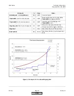
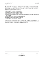
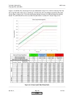
Figure
5
‐
1:
Line
Reactor
Recommendation
‐
VFD
(HP)
vs
Transformer
(kVA)
HOME
Summary of Contents for LMV 5 Series
Page 2: ...Intentionally Left Blank ...
Page 41: ...LMV Series Technical Instructions Document No LV5 1000 SCC Inc Page 7 Section 2 HOME ...
Page 42: ...Technical Instructions LMV Series Document No LV5 1000 Section 2 Page 8 SCC Inc HOME ...
Page 43: ...LMV Series Technical Instructions Document No LV5 1000 SCC Inc Page 9 Section 2 HOME ...
Page 44: ...Technical Instructions LMV Series Document No LV5 1000 Section 2 Page 10 SCC Inc HOME ...
Page 45: ...LMV Series Technical Instructions Document No LV5 1000 SCC Inc Page 11 Section 2 HOME ...
Page 46: ...Technical Instructions LMV Series Document No LV5 1000 Section 2 Page 12 SCC Inc HOME ...
Page 47: ...LMV Series Technical Instructions Document No LV5 1000 SCC Inc Page 13 Section 2 HOME ...
Page 48: ...Technical Instructions LMV Series Document No LV5 1000 Section 2 Page 14 SCC Inc HOME ...
Page 49: ...LMV Series Technical Instructions Document No LV5 1000 SCC Inc Page 15 Section 2 HOME ...
Page 50: ...Technical Instructions LMV Series Document No LV5 1000 Section 2 Page 16 SCC Inc HOME ...
Page 51: ...LMV Series Technical Instructions Document No LV5 1000 SCC Inc Page 17 Section 2 HOME ...
Page 52: ...Technical Instructions LMV Series Document No LV5 1000 Section 2 Page 18 SCC Inc HOME ...
Page 53: ...LMV Series Technical Instructions Document No LV5 1000 SCC Inc Page 19 Section 2 HOME ...
Page 54: ...Technical Instructions LMV Series Document No LV5 1000 Section 2 Page 20 SCC Inc HOME ...
Page 55: ...LMV Series Technical Instructions Document No LV5 1000 SCC Inc Page 21 Section 2 HOME ...
Page 373: ...Intentionally Left Blank ...

