Technical
Instructions
LMV
Series
Document
No.
LV5
‐
1000
Section
5
Page
8
SCC
Inc.
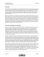
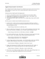
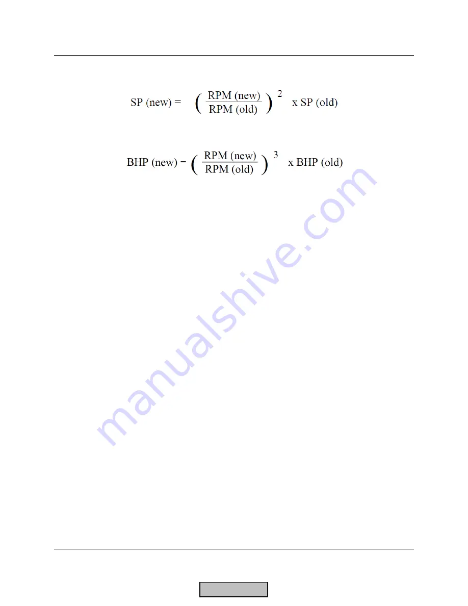
2.
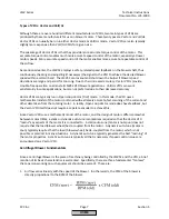
The
static
output
pressure
of
the
blower
(SP)
varies
by
the
square
of
the
change
in
RPM:
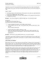
3.
The
required
brake
horsepower
of
the
blower
(BHP)
varies
by
the
cube
of
the
change
in
RPM:
Example:
A
blower
spinning
at
1750
RPM
produces
10
in
WC
of
static
pressure,
4500
CFM
of
flow,
and
requires
20
BHP.
What
happens
if
the
RPM
is
increased
to
2750
RPM?
Assumptions:
Air
damper
is
wide
open,
and
system
effects
(such
as
the
restriction
due
to
the
boiler's
heat
exchanger,
the
burner’s
diffuser,
etc...)
are
not
taken
into
account.
Flow:
CFM
(new)
=
(2750
/
1750)
*
4500
=
7071
CFM
Pressure:
SP
(new)
=
(2750
/
1750)
2
*
10
=
24.7
in
WC
Power:
BHP
(new)
=
(2750
/
1750)
3
*
20
=
78
BHP
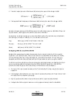
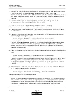
Configuring
VFDs
for
use
with
the
LMV52
Modern
VFDs
typically
have
hundreds
of
parameters
that
can
be
set
to
tailor
the
VFD
to
a
specific
application.
As
mentioned
earlier,
there
are
also
at
least
a
hundred
different
manufacturers
of
VFDs,
each
of
which
have
their
own
unique
parameter
list.
Due
to
these
two
factors,
SCC
Inc.
offers
pre
‐
programmed
VFDs
that
can
be
purchased
with
the
VFD
parameters
set
up
for
use
with
an
LMV52.
If
a
VFD
for
use
with
an
LMV52
is
purchased
and
programmed
independently,
the
following
points
will
serve
as
a
general
guideline
for
programming
the
VFD
for
the
LMV52
application.
Note
that
this
guideline
is
necessarily
general
due
to
the
variety
of
VFDs
offered
in
the
marketplace.
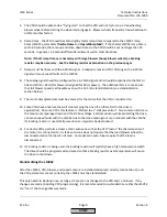
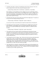
1.
If
a
Vector
VFD
is
used
(recommended),
set
the
"Control
Method"
to
Open
Loop
Vector
mode
or
equivalent.
2.
The
stopping
method
(after
the
run
/
stop
contact
is
opened)
should
be
set
to
"Coast
to
Stop"
to
let
the
motor
coast
to
a
stop
after
post
‐
purge.
3.
Reverse
operation
(the
ability
to
reverse
the
motor
with
an
input)
should
be
disabled.
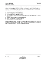
4.
Configure
the
VFD
to
accept
an
external
run
/
stop
signal
via
the
dry
contact
on
the
LMV52.
HOME
Summary of Contents for LMV 5 Series
Page 2: ...Intentionally Left Blank ...
Page 41: ...LMV Series Technical Instructions Document No LV5 1000 SCC Inc Page 7 Section 2 HOME ...
Page 42: ...Technical Instructions LMV Series Document No LV5 1000 Section 2 Page 8 SCC Inc HOME ...
Page 43: ...LMV Series Technical Instructions Document No LV5 1000 SCC Inc Page 9 Section 2 HOME ...
Page 44: ...Technical Instructions LMV Series Document No LV5 1000 Section 2 Page 10 SCC Inc HOME ...
Page 45: ...LMV Series Technical Instructions Document No LV5 1000 SCC Inc Page 11 Section 2 HOME ...
Page 46: ...Technical Instructions LMV Series Document No LV5 1000 Section 2 Page 12 SCC Inc HOME ...
Page 47: ...LMV Series Technical Instructions Document No LV5 1000 SCC Inc Page 13 Section 2 HOME ...
Page 48: ...Technical Instructions LMV Series Document No LV5 1000 Section 2 Page 14 SCC Inc HOME ...
Page 49: ...LMV Series Technical Instructions Document No LV5 1000 SCC Inc Page 15 Section 2 HOME ...
Page 50: ...Technical Instructions LMV Series Document No LV5 1000 Section 2 Page 16 SCC Inc HOME ...
Page 51: ...LMV Series Technical Instructions Document No LV5 1000 SCC Inc Page 17 Section 2 HOME ...
Page 52: ...Technical Instructions LMV Series Document No LV5 1000 Section 2 Page 18 SCC Inc HOME ...
Page 53: ...LMV Series Technical Instructions Document No LV5 1000 SCC Inc Page 19 Section 2 HOME ...
Page 54: ...Technical Instructions LMV Series Document No LV5 1000 Section 2 Page 20 SCC Inc HOME ...
Page 55: ...LMV Series Technical Instructions Document No LV5 1000 SCC Inc Page 21 Section 2 HOME ...
Page 373: ...Intentionally Left Blank ...

