LMV
Series
Technical
Instructions
Document
No.
LV5
‐
1000
SCC
Inc.
Page
25
Section
6
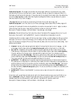
4.
InitContr
–
O
2
control
is
preparing
to
engage
but
is
still
locked
5.
LockTLoad
–
O
2
control
is
engaged
but
locked
(in
pre
‐
control)
due
to
a
load
change
6.
Active
–
O
2
control
is
actively
trimming
based
on
setpoint
and
measured
O
2
value
7.
LockTCAct
‐
O
2
control
is
engaged
but
locked
due
to
an
excursion
from
setpoint
If
the
state
of
the
O
2
control
is
shown
as
"locked",
parameter
Diag
Reg
State
will
show
the
reason
why.
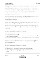
Diag
Reg
State
Menu
path:
Params
&
Display
>
O2
Contr/Alarm
>
Process
Data
This
parameter
shows
the
reason
that
the
O
2
control
is
locked.
Possible
values
are:
0
–
The
load
is
below
the
load
limit
set
by
parameter
O2
CtrlThreshold
1
–
The
load
controller
is
in
auto
tune
2
–
The
O
2
sensor
is
being
tested
for
response
(self
‐
check
of
O
2
sensor)
3
–
The
fuel
‐
air
ratio
or
O
2
trim
curves
are
being
programmed
4
–
The
measured
%
O
2
is
above
the
lean
limit
or
below
the
rich
limit
5
–
There
is
an
error
in
the
PLL52
module
6
–
There
is
an
error
in
the
pre
‐
control
Using
the
O
2
Alarm
Functionality
without
O
2
Trim
As
was
previously
mentioned,
the
O
2
system
can
be
run
in
different
modes.
The
modes
are
set
using
parameter
OptgMode
,
which
can
be
found
using
the
following
menu
path:
Menu
path:
Params
&
Display
>
O2
Contr/Alarm
>
Gas/Oil
Settings
The
available
operating
modes
are:
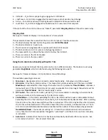
1.
Man
deact
‐
deactivates
all
O
2
trim
and
O
2
alarm
functionality.
%O
2
value
can
still
be
viewed.
2.
O2
Limiter
‐
Only
the
O
2
alarm
is
active.
This
means
that
a
lockout
will
occur
if
the
lean
limit
(
O2
MaxValue
)
is
exceeded
for
a
time
longer
than
what
is
set
for
parameter
Time
O2
Alarm
.
Likewise,
a
lockout
will
occur
if
the
rich
limit
(O
2
alarm
curve)
is
exceeded
for
a
time
longer
than
what
is
set
for
parameter
Time
O2
Alarm
.
No
trim
functionality
is
active.
3.
O2
Control
‐
The
same
as
O2
Limiter,
except
O
2
trim
is
now
enabled.
Exceeding
rich
or
lean
limits
will
cause
a
lockout
in
the
same
way
as
the
O2
Limiter
mode.
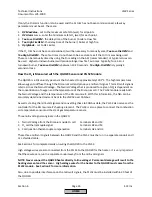
4.
ConAutoDeac
–
In
this
mode,
exceeding
the
rich
or
lean
limits
will
not
cause
an
immediate
lockout.
Exceeding
the
rich
or
lean
limits
will
cause
the
O
2
trim
to
be
temporarily
deactivated.
After
a
waiting
time
of
3
times
Tau,
the
measured
%O
2
will
be
re
‐
evaluated.
If
the
%O
2
is
higher
than
the
rich
alarm,
the
O
2
trim
will
be
deactivated.
If
the
%O
2
is
lower
than
the
rich
alarm,
a
lockout
will
occur.
The
O
2
trim
can
be
automatically
deactivated
and
reactivated
the
number
of
times
allowed
by
parameter
NumMinUntilDeact
.
The
maximum
setting
is
5.
If
more
than
5
deactivations
and
reactivations
occur,
then
the
O
2
trim
mode
will
be
changed
to
“auto
deact”
until
the
O
2
trim
control
is
manually
re
‐
activated.
5.
Auto
deact
‐
indicates
that
the
O
2
trim
has
been
automatically
deactivated
for
some
reason.
See
error
codes
in
Section
7.
Do
not
select
this
mode.
HOME
Summary of Contents for LMV 5 Series
Page 2: ...Intentionally Left Blank ...
Page 41: ...LMV Series Technical Instructions Document No LV5 1000 SCC Inc Page 7 Section 2 HOME ...
Page 42: ...Technical Instructions LMV Series Document No LV5 1000 Section 2 Page 8 SCC Inc HOME ...
Page 43: ...LMV Series Technical Instructions Document No LV5 1000 SCC Inc Page 9 Section 2 HOME ...
Page 44: ...Technical Instructions LMV Series Document No LV5 1000 Section 2 Page 10 SCC Inc HOME ...
Page 45: ...LMV Series Technical Instructions Document No LV5 1000 SCC Inc Page 11 Section 2 HOME ...
Page 46: ...Technical Instructions LMV Series Document No LV5 1000 Section 2 Page 12 SCC Inc HOME ...
Page 47: ...LMV Series Technical Instructions Document No LV5 1000 SCC Inc Page 13 Section 2 HOME ...
Page 48: ...Technical Instructions LMV Series Document No LV5 1000 Section 2 Page 14 SCC Inc HOME ...
Page 49: ...LMV Series Technical Instructions Document No LV5 1000 SCC Inc Page 15 Section 2 HOME ...
Page 50: ...Technical Instructions LMV Series Document No LV5 1000 Section 2 Page 16 SCC Inc HOME ...
Page 51: ...LMV Series Technical Instructions Document No LV5 1000 SCC Inc Page 17 Section 2 HOME ...
Page 52: ...Technical Instructions LMV Series Document No LV5 1000 Section 2 Page 18 SCC Inc HOME ...
Page 53: ...LMV Series Technical Instructions Document No LV5 1000 SCC Inc Page 19 Section 2 HOME ...
Page 54: ...Technical Instructions LMV Series Document No LV5 1000 Section 2 Page 20 SCC Inc HOME ...
Page 55: ...LMV Series Technical Instructions Document No LV5 1000 SCC Inc Page 21 Section 2 HOME ...
Page 373: ...Intentionally Left Blank ...

