Technical
Instructions
LMV
Series
Document
No.
LV5
‐
1000
Section
7
Page
10
SCC
Inc.
Open
Safety
Loop
–
Error
Code
21
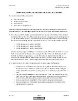
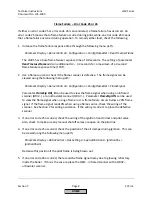
The
safety
loop
is
meant
only
for
safety
limits
such
as
an
auxiliary
low
water
cutout
or
a
high
limit.
The
safety
loop
must
be
complete,
and
cannot
be
reconfigured.
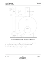
The
wiring
of
the
safety
loop
is
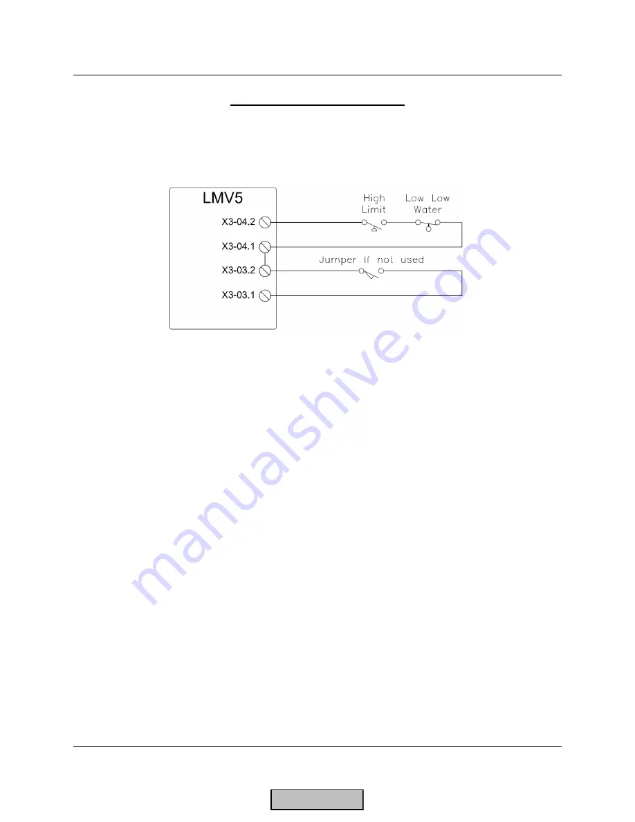
shown
below:
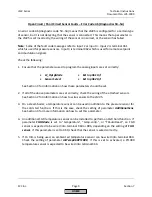
If
an
error
code
21
is
encountered,
check
the
following:
1.
The
burner
flange
switch
wired
between
terminals
X3
‐
03.1
and
X3
‐
03.2.
There
should
be
120
VAC
on
terminal
X3
‐
03.1
at
all
times.
If
a
burner
flange
switch
is
not
present,
a
jumper
must
be
placed
between
terminals
X3
‐
03.1
and
X3
‐
03.2.
2.
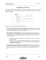
Operating
switches
in
the
safety
loop
.
Operating
(cycling)
switches
should
not
be
wired
into
the
safety
loop.
If
a
cycling
switch
is
placed
in
this
loop
and
it
cycles
off,
the
LMV5
will
lockout.
The
cycling
switch
should
be
relocated
in
series
with
the
burner
on
/
off
switch
wired
to
X5
‐
03.1:
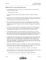
If
the
LMV5
is
in
any
external
load
controller
mode
(
ExtLC
…),
this
is
used
to
cycle
the
burner
on
and
off.
If
the
LMV5
is
in
any
internal
load
controller
mode
(
IntLC
…),
then
a
cycling
switch
may
not
be
necessary,
since
this
is
done
automatically
in
the
LMV5
using
parameters
SD_ModOn
and
SD_ModOff
.
3.
The
safety
loop
between
terminals
X3
‐
04.1
and
X3
‐
04.2.
There
should
be
120
VAC
on
terminal
X3
‐
04.1
at
all
times.
If
there
is
not,
then
one
or
more
of
the
devices
wired
into
the
safety
loop
are
open.
Check
each
device
wired
into
the
safety
loop
to
find
which
one
is
open.
HOME
Summary of Contents for LMV 5 Series
Page 2: ...Intentionally Left Blank ...
Page 41: ...LMV Series Technical Instructions Document No LV5 1000 SCC Inc Page 7 Section 2 HOME ...
Page 42: ...Technical Instructions LMV Series Document No LV5 1000 Section 2 Page 8 SCC Inc HOME ...
Page 43: ...LMV Series Technical Instructions Document No LV5 1000 SCC Inc Page 9 Section 2 HOME ...
Page 44: ...Technical Instructions LMV Series Document No LV5 1000 Section 2 Page 10 SCC Inc HOME ...
Page 45: ...LMV Series Technical Instructions Document No LV5 1000 SCC Inc Page 11 Section 2 HOME ...
Page 46: ...Technical Instructions LMV Series Document No LV5 1000 Section 2 Page 12 SCC Inc HOME ...
Page 47: ...LMV Series Technical Instructions Document No LV5 1000 SCC Inc Page 13 Section 2 HOME ...
Page 48: ...Technical Instructions LMV Series Document No LV5 1000 Section 2 Page 14 SCC Inc HOME ...
Page 49: ...LMV Series Technical Instructions Document No LV5 1000 SCC Inc Page 15 Section 2 HOME ...
Page 50: ...Technical Instructions LMV Series Document No LV5 1000 Section 2 Page 16 SCC Inc HOME ...
Page 51: ...LMV Series Technical Instructions Document No LV5 1000 SCC Inc Page 17 Section 2 HOME ...
Page 52: ...Technical Instructions LMV Series Document No LV5 1000 Section 2 Page 18 SCC Inc HOME ...
Page 53: ...LMV Series Technical Instructions Document No LV5 1000 SCC Inc Page 19 Section 2 HOME ...
Page 54: ...Technical Instructions LMV Series Document No LV5 1000 Section 2 Page 20 SCC Inc HOME ...
Page 55: ...LMV Series Technical Instructions Document No LV5 1000 SCC Inc Page 21 Section 2 HOME ...
Page 373: ...Intentionally Left Blank ...

