Technical
Instructions
LMV
Series
Document
No.
LV5
‐
1000
Section
7
Page
12
SCC
Inc.
LMV5
Will
Not
Modulate
Properly
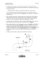
1.
Ensure
that
the
LMV5
is
in
automatic
mode
through
the
following
menu
path:
ManualOperation
>
Autom/Manual/Off
=
Automatic
2.
Check
the
PID
settings
and
make
sure
that
they
are
set
for
the
application.
P
‐
Part
–
This
is
the
proportional
band.
The
proportional
band
increases
firing
rate
based
on
how
far
below
setpoint
the
temperature
/
pressure
is.
Smaller
values
cause
a
more
aggressive
response
to
a
drop
in
pressure
/
temperature
relative
to
setpoint.
Values
that
are
too
small
will
cause
hunting.
Typical
setting:
10%
to
30%.
I
‐
Part
–
This
is
the
integral
part
,
which
serves
to
eliminate
steady
state
"droop"
caused
by
the
proportional
band
setting.
Thus,
this
works
hand
in
hand
with
P
‐
Part
to
bring
the
pressure
/
temperature
up
to
setpoint.
Smaller
values
cause
a
more
aggressive
response
(a
setting
of
1
is
most
aggressive).
Values
that
are
too
small
will
cause
overshoot.
Typical
setting:
80
sec
to
300
sec.
A
setting
of
0
deactivates
the
feature,
but
this
is
not
recommended.
D
‐
Part
–
This
is
the
derivative
part
,
which
serves
to
eliminate
overshoot,
and
allows
a
more
aggressive
integral
setting.
Larger
values
cause
a
more
aggressive
response.
D
‐
Part
is
not
needed
on
many
steam
boilers.
If
needed,
small
values
of
less
than
20
typically
work
well.
A
setting
of
0
deactivates
the
feature.
Large
values
will
typically
cause
hunting.
3.
Check
the
load
limit
parameters
(
UserMaxLoad
,
MinLoad
,
MaxLoad
)
to
verify
that
they
are
not
limiting
modulation.
4.
Check
the
load
mask
parameters
under
each
fuel
and
verify
that
they
are
not
preventing
modulation.
These
can
be
checked
using
the
following
menu
path:
Params
&
Display
>
RatioControl
>
Gas/Oil
Settings
>
LoadLimits
Default
values
are:
LoadMaskLowLimit
=
0%,
LoadMaskHighLimit
=
0%.
5.
If
the
LMV5
goes
to
high
fire
in
phase
52,
check
parameter
StartPointOp
under
each
fuel.
This
should
typically
be
set
to
1
(low
fire).
Note:
If
PID
values
are
set
properly,
the
load
should
change
no
more
than
once
every
8
seconds
on
most
installations.
If
PID
values
are
set
improperly,
the
duty
cycle
of
the
SQM…
actuator
can
be
exceeded.
HOME
Summary of Contents for LMV 5 Series
Page 2: ...Intentionally Left Blank ...
Page 41: ...LMV Series Technical Instructions Document No LV5 1000 SCC Inc Page 7 Section 2 HOME ...
Page 42: ...Technical Instructions LMV Series Document No LV5 1000 Section 2 Page 8 SCC Inc HOME ...
Page 43: ...LMV Series Technical Instructions Document No LV5 1000 SCC Inc Page 9 Section 2 HOME ...
Page 44: ...Technical Instructions LMV Series Document No LV5 1000 Section 2 Page 10 SCC Inc HOME ...
Page 45: ...LMV Series Technical Instructions Document No LV5 1000 SCC Inc Page 11 Section 2 HOME ...
Page 46: ...Technical Instructions LMV Series Document No LV5 1000 Section 2 Page 12 SCC Inc HOME ...
Page 47: ...LMV Series Technical Instructions Document No LV5 1000 SCC Inc Page 13 Section 2 HOME ...
Page 48: ...Technical Instructions LMV Series Document No LV5 1000 Section 2 Page 14 SCC Inc HOME ...
Page 49: ...LMV Series Technical Instructions Document No LV5 1000 SCC Inc Page 15 Section 2 HOME ...
Page 50: ...Technical Instructions LMV Series Document No LV5 1000 Section 2 Page 16 SCC Inc HOME ...
Page 51: ...LMV Series Technical Instructions Document No LV5 1000 SCC Inc Page 17 Section 2 HOME ...
Page 52: ...Technical Instructions LMV Series Document No LV5 1000 Section 2 Page 18 SCC Inc HOME ...
Page 53: ...LMV Series Technical Instructions Document No LV5 1000 SCC Inc Page 19 Section 2 HOME ...
Page 54: ...Technical Instructions LMV Series Document No LV5 1000 Section 2 Page 20 SCC Inc HOME ...
Page 55: ...LMV Series Technical Instructions Document No LV5 1000 SCC Inc Page 21 Section 2 HOME ...
Page 373: ...Intentionally Left Blank ...

