LMV
Series
Technical
Instructions
Document
No.
LV5
‐
1000
SCC
Inc.
Page
13
Section
7
O2
Sensor
is
Not
Reading
If
the
O
2
value
on
the
main
screen
is
displayed
as
“XXXX”,
check
the
following:
1.
Ensure
that
the
QGO20
O
2
sensor
is
activated
through
the
following
menu
path:
Params
&
Display
>
O2
Module
>
Configuration
>
O2
Sensor
=
QGO20
2.
The
PLL52
O
2
module
controls
the
QGO20
O
2
sensor’s
heater
to
achieve
a
sensor
temperature
of
approximately
1292
o
F.
The
sensor
cannot
read
%O
2
if
the
sensor
is
below
1202
o
F.
Check
the
temperature
of
the
QGO20
sensor
through
the
following
menu
path:
Params
&
Display
>
O2
Module
>
Process
Data
>
QGO
SensorTemp
If
the
temperature
is
below
1202
°F,
check
the
heating
load
to
the
O
2
sensor:
Params
&
Display
>
O2
Module
>
Process
Data
>
QGO
HeatingLoad
The
maximum
QGO
heating
load
is
60%.
If
the
heating
load
is
at
or
near
60%,
the
QGO20
sensor
temperature
should
be
increasing.
If
it
is,
the
O
2
sensor
will
begin
reading
once
the
temperature
is
over
1202
°F.
If
the
temperature
is
not
increasing,
check
the
following:
The
stack
velocity
may
be
too
high,
thus
cooling
the
sensor.
The
maximum
stack
velocity
is
33
ft
/
second.
The
wiring
between
the
O
2
sensor
and
the
PLL52
O
2
module
may
be
incorrect.
Refer
to
Section
2
to
check
the
wiring
between
the
two
devices.
The
heating
element
in
the
QGO20
O
2
sensor
may
be
damaged.
Measure
the
resistance
between
terminals
Q4
and
Q5
on
the
QGO20
O
2
sensor.
There
should
be
between
5
and
150
Ohms
between
these
terminals.
If
there
is
an
open
circuit
between
these
two
terminals,
the
heating
element
has
been
damaged
and
the
QGO20
O
2
sensor
needs
to
be
replaced.
Note:
The
QGO20
sensor
can
take
up
to
two
hours
to
achieve
operating
temperature
on
the
initial
startup.
HOME
Summary of Contents for LMV 5 Series
Page 2: ...Intentionally Left Blank ...
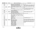
Page 41: ...LMV Series Technical Instructions Document No LV5 1000 SCC Inc Page 7 Section 2 HOME ...
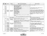
Page 42: ...Technical Instructions LMV Series Document No LV5 1000 Section 2 Page 8 SCC Inc HOME ...
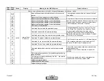
Page 43: ...LMV Series Technical Instructions Document No LV5 1000 SCC Inc Page 9 Section 2 HOME ...
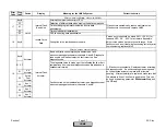
Page 44: ...Technical Instructions LMV Series Document No LV5 1000 Section 2 Page 10 SCC Inc HOME ...
Page 45: ...LMV Series Technical Instructions Document No LV5 1000 SCC Inc Page 11 Section 2 HOME ...
Page 46: ...Technical Instructions LMV Series Document No LV5 1000 Section 2 Page 12 SCC Inc HOME ...
Page 47: ...LMV Series Technical Instructions Document No LV5 1000 SCC Inc Page 13 Section 2 HOME ...
Page 48: ...Technical Instructions LMV Series Document No LV5 1000 Section 2 Page 14 SCC Inc HOME ...
Page 49: ...LMV Series Technical Instructions Document No LV5 1000 SCC Inc Page 15 Section 2 HOME ...
Page 50: ...Technical Instructions LMV Series Document No LV5 1000 Section 2 Page 16 SCC Inc HOME ...
Page 51: ...LMV Series Technical Instructions Document No LV5 1000 SCC Inc Page 17 Section 2 HOME ...
Page 52: ...Technical Instructions LMV Series Document No LV5 1000 Section 2 Page 18 SCC Inc HOME ...
Page 53: ...LMV Series Technical Instructions Document No LV5 1000 SCC Inc Page 19 Section 2 HOME ...
Page 54: ...Technical Instructions LMV Series Document No LV5 1000 Section 2 Page 20 SCC Inc HOME ...
Page 55: ...LMV Series Technical Instructions Document No LV5 1000 SCC Inc Page 21 Section 2 HOME ...
Page 373: ...Intentionally Left Blank ...

