LMV Series
Technical Instructions
LV5-1000
Menu Path
Parameter
Default
Range
Description
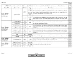
51.1
52.2
52.4
LEGEND -
Password Access:
(U)=User, (S)=Service, (O)=OEM, Shaded = Commonly Used, ** = Must Set, X = Has Function, / = Partial Function
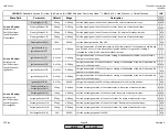
LMV
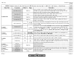
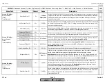
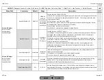
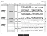
Standardize (O)
Sets a datum for a "normal" flame, so that a "normal" flame can be displayed as 100% flame
signal on the OperationalStat screen. If an 82.3% flame is present and the flame
standardization is performed, what was displayed as 82.3% is now displayed as 100%. This
parameter does not affect when a lockout occurs due to low flame signal. This standarization
is performed when a normal flame exists in the burner.
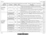
StandardFactor (O)
XXXX%
(Not Set)
0-100%
Can be viewed to see what percent raw flame signal will result in 100% flame signal being
displayed on the OperationalStat screen. If the flame signal is not standardized, XXXX % will
appear, indicating actual flame strength is displayed.
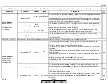
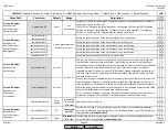
FlameSig QRI_B (U)
This can be viewed to see the raw flame signal (in %) from the flame scanner (IR or UV).
Flame failure at 20%. This signal refers to INPUT terminal X10-02.1 or X10-02.2.
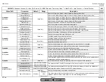
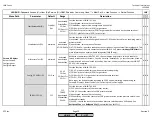
FlameSig ION (U)
This can be viewed to see what raw flame signal (in %) is being sent to the LMV5 by an
ionization probe (flame rod) on terminal X10-03.1. The LMV5 will alarm when this value is
less than about 20%.
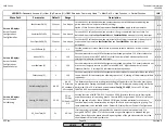
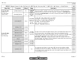
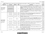
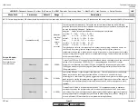
SensExtranlGas (O)
1 Sensor
See
Description
For the LMV52, this defines how the combustion chamber will be supervised during the
period when the fuel valves are closed (gas firing).
The choices for supervision during this phase are as follows:
1) 1 Sensor: Either a flame rod (ION) or scanner can be connected and used. Both cannot be
connected.
2) QRI_B | ION: Both sensors can be connected. A flame signal on either will cause a signal
to be registered.
3) QRI_B & /ION: Both sensors can be connected. Flame must be detected by QRI_B and not
ION.
4) QRI_B: Both sensors can be connected. Only QRI_B is used.
5) ION &/QRI_B: Both sensors can be connected. Flame must be detected by ION and not
QRI_B.
6) ION: Both sensors can be connected. Only ION is used.
x x
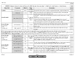
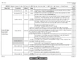
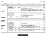
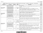
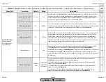
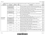
SensPilotPhGas (O)
1 Sensor
See Above
For the LMV52, this defines how the pilot for gas firing is supervised. Options 1 thru 6 as
described in parameter
SenExtranlGas
also apply to this parameter. Additionally, there is
one option added for this parameter. This option is:
7) QRI_B & ION: Both sensors can be connected. Both sensors must detect a flame at the
same time or a flame failure will occur.
x x
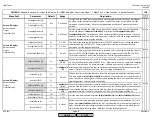
SensOperPhGas (O)
1 Sensor
See Above
For the LMV52, this defines how the main flame for gas firing is supervised. Options 1 thru 7
as described in parameters
SensExtranlGas
and
SensPilotPhGas
also apply to this
parameter.
x x
x x x
Params & Display>
BurnerControl>
Configuration>
ConfigFlameDet
Params & Display>
BurnerControl>
Configuration>
ConfigFlameDet>
FlameSignal
Go into parameter then
press Enter to start
Read Only
Read Only
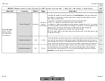
NOTE: On an LMV52, it is recommended to set the following six flame scanner parameters for "1 Sensor". These parameters are unavailable on an LMV51.
SCC Inc.
Page 15
Section 3
HOME
HOME
P - LIST
Summary of Contents for LMV 5 Series
Page 2: ...Intentionally Left Blank ...
Page 41: ...LMV Series Technical Instructions Document No LV5 1000 SCC Inc Page 7 Section 2 HOME ...
Page 42: ...Technical Instructions LMV Series Document No LV5 1000 Section 2 Page 8 SCC Inc HOME ...
Page 43: ...LMV Series Technical Instructions Document No LV5 1000 SCC Inc Page 9 Section 2 HOME ...
Page 44: ...Technical Instructions LMV Series Document No LV5 1000 Section 2 Page 10 SCC Inc HOME ...
Page 45: ...LMV Series Technical Instructions Document No LV5 1000 SCC Inc Page 11 Section 2 HOME ...
Page 46: ...Technical Instructions LMV Series Document No LV5 1000 Section 2 Page 12 SCC Inc HOME ...
Page 47: ...LMV Series Technical Instructions Document No LV5 1000 SCC Inc Page 13 Section 2 HOME ...
Page 48: ...Technical Instructions LMV Series Document No LV5 1000 Section 2 Page 14 SCC Inc HOME ...
Page 49: ...LMV Series Technical Instructions Document No LV5 1000 SCC Inc Page 15 Section 2 HOME ...
Page 50: ...Technical Instructions LMV Series Document No LV5 1000 Section 2 Page 16 SCC Inc HOME ...
Page 51: ...LMV Series Technical Instructions Document No LV5 1000 SCC Inc Page 17 Section 2 HOME ...
Page 52: ...Technical Instructions LMV Series Document No LV5 1000 Section 2 Page 18 SCC Inc HOME ...
Page 53: ...LMV Series Technical Instructions Document No LV5 1000 SCC Inc Page 19 Section 2 HOME ...
Page 54: ...Technical Instructions LMV Series Document No LV5 1000 Section 2 Page 20 SCC Inc HOME ...
Page 55: ...LMV Series Technical Instructions Document No LV5 1000 SCC Inc Page 21 Section 2 HOME ...
Page 373: ...Intentionally Left Blank ...

