LMV Series
Technical Instructions
LV5-1000
Menu Path
Parameter
Default
Range
Description
51.1
52.2
52.4
LEGEND -
Password Access:
(U)=User, (S)=Service, (O)=OEM, Shaded = Commonly Used, ** = Must Set, X = Has Function, / = Partial Function
LMV
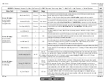
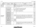
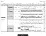
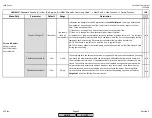
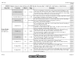
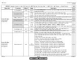
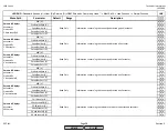
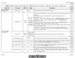
MinActuatorStep (U)
1%
0.5-10%
This serves as a deadband on the output of the PID loop to eliminate hunting due to small
load changes. If the PID loop requires a load change less than the setting of this parameter,
the load will not change. Settings of 5% or above may be counterproductive, not permitting
the boiler to closely match the load which may also cause hunting.
x x x
SW_FilterTmeCon (U)
3s
1-10s
This dampens the pressure or temperature that the LMV5 is reading. Higher values increase
the damping and will steady small oscillations in the reading.
x x x
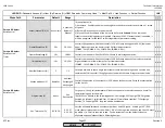
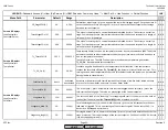
SetpointW1 (U)
0
Sensor Range
W1 is the primary setpoint of the boiler, in units of temperature or pressure depending on
the sensor attached to the LMV5. Setpoint is changed via the AZL52.
Also access at:
Operation > BoilerSetpoint
.
x x x
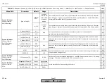
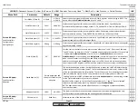
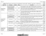
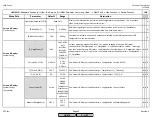
SetpointW2 (U)
0
Sensor Range
W2 is a secondary setpoint of the boiler, in units of temperature or pressure depending on
the sensor attached to the LMV5.
Also access at:
Operation > BoilerSetpoint
.
If the LMV5 is in internal load controller mode 2 (IntLC), the setpoint can be switched to W2
(from W1) by closing a contact between X62.1 and X62.2.
x x x
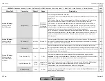
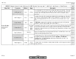
SD_ModOn (U)
1%
-50-50%
Determines what temp. / press. a modulating burner will cycle on when LMV5 is in any
internal load controller mode. Ignored in external load controller modes.
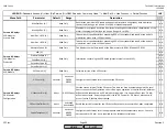
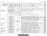
Can be set at a positive or negative %, either above or below the current setpoint
respectively. Percentage based on current setpoint.
x x x
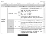
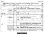
SD_ModOff (U)
10%
0-50%
Determines what temp. / press. a modulating burner will cycle off when LMV5 is in any
internal load controller mode. Ignored in external load controller modes.
Can be set at a positive or negative %, either above or below the current setpoint
respectively. Percentage based on current setpoint.
x x x
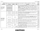
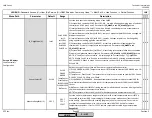
SD_Stage1On (U)
-2%
-50-50%
Determines what temp. / press. a staged oil burner will engage stage 1.
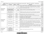
Set at a negative %, so that the burner will turn on stage 1 at a set % below the current
setpoint. Percentage based on current setpoint.
x x x
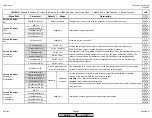
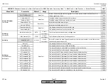
SD_Stage1Off (U)
10%
0-50%
Determines what temp. / press. a staged oil burner will disengage stage 1.
Set at a positive % so that the burner will turn off stage 1 oil at a set % above the current
setpoint. Percentage based on current setpoint.
x x x
SD_Stage2Off (U)
8%
0-50%
Determines what temp. / press. a staged oil burner will disengage stage 2. Set at a positive %
so that the boiler will turn off stage 2 oil at a set % above the current setpoint. Percentage
based on current setpoint.
x x x
Params & Display>
LoadController>
ControllerParam
SCC Inc.
Page 30
Section 3
HOME
HOME
P - LIST
Summary of Contents for LMV 5 Series
Page 2: ...Intentionally Left Blank ...
Page 41: ...LMV Series Technical Instructions Document No LV5 1000 SCC Inc Page 7 Section 2 HOME ...
Page 42: ...Technical Instructions LMV Series Document No LV5 1000 Section 2 Page 8 SCC Inc HOME ...
Page 43: ...LMV Series Technical Instructions Document No LV5 1000 SCC Inc Page 9 Section 2 HOME ...
Page 44: ...Technical Instructions LMV Series Document No LV5 1000 Section 2 Page 10 SCC Inc HOME ...
Page 45: ...LMV Series Technical Instructions Document No LV5 1000 SCC Inc Page 11 Section 2 HOME ...
Page 46: ...Technical Instructions LMV Series Document No LV5 1000 Section 2 Page 12 SCC Inc HOME ...
Page 47: ...LMV Series Technical Instructions Document No LV5 1000 SCC Inc Page 13 Section 2 HOME ...
Page 48: ...Technical Instructions LMV Series Document No LV5 1000 Section 2 Page 14 SCC Inc HOME ...
Page 49: ...LMV Series Technical Instructions Document No LV5 1000 SCC Inc Page 15 Section 2 HOME ...
Page 50: ...Technical Instructions LMV Series Document No LV5 1000 Section 2 Page 16 SCC Inc HOME ...
Page 51: ...LMV Series Technical Instructions Document No LV5 1000 SCC Inc Page 17 Section 2 HOME ...
Page 52: ...Technical Instructions LMV Series Document No LV5 1000 Section 2 Page 18 SCC Inc HOME ...
Page 53: ...LMV Series Technical Instructions Document No LV5 1000 SCC Inc Page 19 Section 2 HOME ...
Page 54: ...Technical Instructions LMV Series Document No LV5 1000 Section 2 Page 20 SCC Inc HOME ...
Page 55: ...LMV Series Technical Instructions Document No LV5 1000 SCC Inc Page 21 Section 2 HOME ...
Page 373: ...Intentionally Left Blank ...

