LMV Series
Technical Instructions
LV5-1000
Menu Path
Parameter
Default
Range
Description
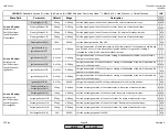
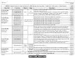
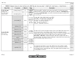
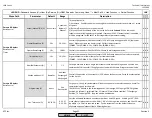
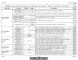
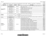
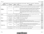
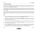
51.1
52.2
52.4
LEGEND -
Password Access:
(U)=User, (S)=Service, (O)=OEM, Shaded = Commonly Used, ** = Must Set, X = Has Function, / = Partial Function
LMV
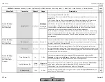
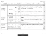
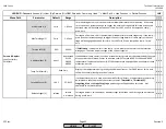
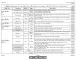
MaxTmeMod (S)
3min
1-63min
For modulating burners, this is the maximum allowable time for each load step. If the temp.
/ press. does not increase enough to trigger the next load step before this time expires, the
next load step will be taken based on this time. Set to 63 min if to be ramped on temp. /
press. only.
x x x
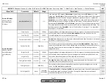
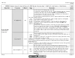
MaxTmeStage (S)
3min
1-63min
For staged oil burners, this is the maximum allowable time for each stage step. If the temp. /
press. does not increase enough to trigger the next stage before this time expires, the next
stage will be engaged based on this time. Set to 63 min if to be ramped on temp. / press.
only.
x x x
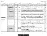
ThresholdOff (S)
80%
0-100%
If
ColdStartOn
is activated, this is the temp. / press. where the thermal shock protection
disengages. The value is a percentage of the current setpoint.
x x x
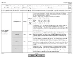
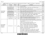
AdditionalSens (S)
deact
deactivated
Pt100
Pt1000
Ni1000
If an additional temp sensor is used on a steam boiler for cold start (recommended), the type
of sensor must be selected. Sensor to be wired to INPUT terminal X60. Pt1000 and Ni1000
temperature is updated continuously, PT100 temperature only updated when thermal shock
protection is active.
x x x
Temp. ColdStart (U)
Displays the temperature being read by the additional sensor. For Pt100 sensor, this is only
valid when thermal shock protection is active.
x x x
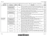
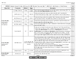
Setp AddSensor (S)
140 F
32-842 F
If a temperature sensor is used on a steam boiler for cold start, a temperature setpoint must
be selected to take the place of the current setpoint.
ThresholdOn
,
ThresholdOff
,
StageSetp_Mod
, and
StageSetp_Stage
percentages will be based on this value. Not
applicable to hot water boilers.
x x x
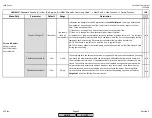
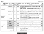
Release Stages (S)
release
release
no release
For staged burners, this enables or disables stages (other than the first stage) to be released
during a cold start.
x x x
Read Only
Params & Display>
LoadController>
ColdStart
SCC Inc.
Page 32
Section 3
HOME
HOME
P - LIST
Summary of Contents for LMV 5 Series
Page 2: ...Intentionally Left Blank ...
Page 41: ...LMV Series Technical Instructions Document No LV5 1000 SCC Inc Page 7 Section 2 HOME ...
Page 42: ...Technical Instructions LMV Series Document No LV5 1000 Section 2 Page 8 SCC Inc HOME ...
Page 43: ...LMV Series Technical Instructions Document No LV5 1000 SCC Inc Page 9 Section 2 HOME ...
Page 44: ...Technical Instructions LMV Series Document No LV5 1000 Section 2 Page 10 SCC Inc HOME ...
Page 45: ...LMV Series Technical Instructions Document No LV5 1000 SCC Inc Page 11 Section 2 HOME ...
Page 46: ...Technical Instructions LMV Series Document No LV5 1000 Section 2 Page 12 SCC Inc HOME ...
Page 47: ...LMV Series Technical Instructions Document No LV5 1000 SCC Inc Page 13 Section 2 HOME ...
Page 48: ...Technical Instructions LMV Series Document No LV5 1000 Section 2 Page 14 SCC Inc HOME ...
Page 49: ...LMV Series Technical Instructions Document No LV5 1000 SCC Inc Page 15 Section 2 HOME ...
Page 50: ...Technical Instructions LMV Series Document No LV5 1000 Section 2 Page 16 SCC Inc HOME ...
Page 51: ...LMV Series Technical Instructions Document No LV5 1000 SCC Inc Page 17 Section 2 HOME ...
Page 52: ...Technical Instructions LMV Series Document No LV5 1000 Section 2 Page 18 SCC Inc HOME ...
Page 53: ...LMV Series Technical Instructions Document No LV5 1000 SCC Inc Page 19 Section 2 HOME ...
Page 54: ...Technical Instructions LMV Series Document No LV5 1000 Section 2 Page 20 SCC Inc HOME ...
Page 55: ...LMV Series Technical Instructions Document No LV5 1000 SCC Inc Page 21 Section 2 HOME ...
Page 373: ...Intentionally Left Blank ...

