LMV Series
Technical Instructions
LV5-1000
Menu Path
Parameter
Default
Range
Description
51.1
52.2
52.4
LEGEND -
Password Access:
(U)=User, (S)=Service, (O)=OEM, Shaded = Commonly Used, ** = Must Set, X = Has Function, / = Partial Function
LMV
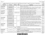
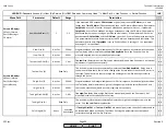
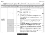
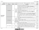
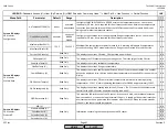
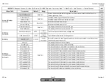
LC_OptgMode (U)
IntLC
ExtLC X5-03
IntLC
IntLC Bus
IntLC X62
ExtLC X62
ExtLC Bus
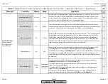
Sets the load controller operating mode of the LMV5.
1) External load controller X5-03 (ExtLC X5-03) - use with a floating bumping type of universal
controller on X5-03 pins 2 and 3. Parameters
SD_ModOn
and
SD_ModOff
ignored.
2) Internal load controller (IntLC) - use with a directly connected pressure or temperature
sensor. Setpoint W1 is normally used with this mode.
3) Internal load controller Bus (IntLC Bus) - same as 2 except setpoint W3 can be changed via
Modbus connection.
4) Internal load controller X62 (IntLC X62) - same as 2 except setpoint can be changed by
using an external analog signal on terminal X62.
5) External load controller X62 (ExtLC X62) - direct firing rate control analog signal on
terminal X62. Pressure / temperature sensors ignored. Parameters
SD_ModOn
and
SD_ModOff
ignored.
6) External load controller Bus (ExtLC Bus) - direct firing rate control via Modbus connection.
Pressure / temperature sensors ignored. Parameters
SD_ModOn
and
SD_ModOff
ignored.
NOTE: If "Load Controller not active" is displayed, go to:
SystemConfig > LC_OptgMode
.
NOTE: Modes 1 and 3 thru 6 can be switched back to mode 2 by closing a contact between
X62.1 and X62.2. When in mode 2, contact closure can be used to switch between setpoint
W1 and W2.
x x x
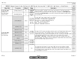
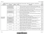
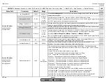
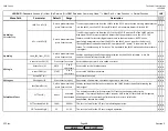
Sensor Select (S)
Pt100
Pt100
Pt1000
Ni1000
TempSensor
PressSensor
Pt100Pt1000
Pt100Ni1000
NoSensor
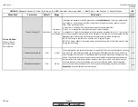
Defines the type of sensor that will be used for the internal load controller.
1) Pt100, Pt1000, Ni1000 - Temperature sensor (RTD) wired to terminal X60. Ni1000 is an LG-
Ni1000 sensor.
2) TempSensor, PressSensor - Temperature or pressure sensor wired to terminal X61. Can be
0-10VDC, 2-10VDC, 0-20mA or 4-20mA.
3) Pt100Pt1000, Pt100Ni1000 - Redundant temperature sensors wired to terminal X60 for
hot water boilers. Reduntant temp sensor for temperature limiter. Ni1000 is an LG-Ni1000
sensor.
4) NoSensor - Selected if LMV5x is being remotely modulated and no sensor is being used for
the load controller or the temperature limiter.
NOTE: Temperature limiter is only active for hot water boilers (temperature control).
x x x
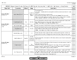
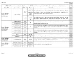
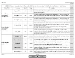
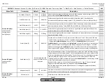
MeasureRangePtNi (S)
302 F
302 F
752 F
1562 F
Sets the end of measurement range for platinum or LG-nickel temperature sensors (RTDs)
connected to terminal X60. Lower settings will detect sensor malfunctions (short circuits)
more quickly. Does not affect the scaling (degrees / ohm) for the sensors. Set as low as
practical for the application. Also, this serves to scale INPUT X62 if used for remote
temperature setpoints. If set for 1562F, remote setpoints are scaled by parameter
var.
RangePtNi
.
x x x
Params & Display>
LoadController>
Configuration
SCC Inc.
Page 33
Section 3
HOME
HOME
P - LIST
Summary of Contents for LMV 5 Series
Page 2: ...Intentionally Left Blank ...
Page 41: ...LMV Series Technical Instructions Document No LV5 1000 SCC Inc Page 7 Section 2 HOME ...
Page 42: ...Technical Instructions LMV Series Document No LV5 1000 Section 2 Page 8 SCC Inc HOME ...
Page 43: ...LMV Series Technical Instructions Document No LV5 1000 SCC Inc Page 9 Section 2 HOME ...
Page 44: ...Technical Instructions LMV Series Document No LV5 1000 Section 2 Page 10 SCC Inc HOME ...
Page 45: ...LMV Series Technical Instructions Document No LV5 1000 SCC Inc Page 11 Section 2 HOME ...
Page 46: ...Technical Instructions LMV Series Document No LV5 1000 Section 2 Page 12 SCC Inc HOME ...
Page 47: ...LMV Series Technical Instructions Document No LV5 1000 SCC Inc Page 13 Section 2 HOME ...
Page 48: ...Technical Instructions LMV Series Document No LV5 1000 Section 2 Page 14 SCC Inc HOME ...
Page 49: ...LMV Series Technical Instructions Document No LV5 1000 SCC Inc Page 15 Section 2 HOME ...
Page 50: ...Technical Instructions LMV Series Document No LV5 1000 Section 2 Page 16 SCC Inc HOME ...
Page 51: ...LMV Series Technical Instructions Document No LV5 1000 SCC Inc Page 17 Section 2 HOME ...
Page 52: ...Technical Instructions LMV Series Document No LV5 1000 Section 2 Page 18 SCC Inc HOME ...
Page 53: ...LMV Series Technical Instructions Document No LV5 1000 SCC Inc Page 19 Section 2 HOME ...
Page 54: ...Technical Instructions LMV Series Document No LV5 1000 Section 2 Page 20 SCC Inc HOME ...
Page 55: ...LMV Series Technical Instructions Document No LV5 1000 SCC Inc Page 21 Section 2 HOME ...
Page 373: ...Intentionally Left Blank ...

