background image


37/39 

Smart Infrastructure  

LMV6 Installation Guide 

CC1J7560en 


12 Commissioning 

4/21/2020 

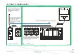
12.2 Variant for parallel operation 


Figure 31: Variant for parallel operation 


Summary of Contents for LMV60.110A2

Page 1: ...Guide The LMV6 and this Installation Guide are intended for original equipment manufacturers OEMs using the LMV6 in or on their products Please note All the safety warning and technical notes given in the basic documentation for the LMV6 P7560 also apply to this document in full Failure to observe this poses a risk of damaging the safety functions and the risk of electric shock ...

Page 2: ...60 LMV6 Burner management system Product Range Overview Q7560 On request only Note This document only refers to the product type not the product designation See the table below for details Product type Product designation AGG6 200A5 100 to 240 V power supply unit AGG6 500 Shielding plate AGG6 635 Ready fitted CAN bus connecting cable AGG6 641 CAN bus connecting cable AGG9 Connector set AZL66 Displ...

Page 3: ... 2 1 Terminal X13 17 3 2 2 Terminal X161 17 4 Block diagram inputs outputs 18 5 AZL66 connection assignment 19 6 SQM4 connection assignment 19 7 AGG6 200A5 connection assignment 20 8 Earthing and shielding of the LMV6 21 8 1 Earthing 21 8 1 1 Protective earth PE 21 8 1 2 Functional earth FE 22 8 1 3 EMC compliant wiring 23 8 1 4 Earthing and wiring of the LMV6 24 8 2 Earthing systems 27 8 2 1 TN e...

Page 4: ...4 39 Smart Infrastructure LMV6 Installation Guide CC1J7560en 4 21 2020 12 1 Parallel operation 36 12 2 Variant for parallel operation 37 13 List of figures 38 ...

Page 5: ...ts Mains power may only be supplied via L and N There must be no difference in potential between the neutral conductor N and protective earth PE Circuit breakers should have a characteristic C when operated with the LMV6 Make certain that strain relief of the connected cables is in compliance with the relevant standards e g as per DIN EN 60730 and DIN EN 60335 Ensure that spliced wires cannot come...

Page 6: ...n probe does not offer protection against electric shock hazards Protection against accidental contact must be ensured Failure to observe this information poses a risk of electric shock Position the ignition electrode and the ionization probe in such a way that the ignition spark cannot arc over to the ionization probe risk of electrical overloads and adversely affect the ionization supervision pr...

Page 7: ...7 39 Smart Infrastructure LMV6 Installation Guide CC1J7560en 2 Assignment of connections 4 21 2020 2 Assignment of connections 2 1 LMV60 110A2 Figure 1 LMV60 110A2 connection assignment ...

Page 8: ...020 2 2 Protection classes 2 2 1 LMV6 Figure 2 LMV6 protection classes Please note Degree of protection IP40 The LMV6 offers degree of protection IP00 The burner or boiler manufacturer must ensure degree of protection IP40 for the LMV6 in accordance with DIN EN 60529 through adequate installation ...

Page 9: ...1 2020 2 2 2 AGG6 200 Figure 3 AGG6 200 protection classes Please note Degree of protection IP40 The AGG6 200 offers degree of protection IP00 The burner or boiler manufacturer must ensure degree of protection IP40 for the AGG6 200 in accordance with DIN EN 60529 through adequate installation ...

Page 10: ...Data Parameter Parameter number impacting the function or behavior of the inputs outputs 3 1 LMV6 3 1 1 Terminal X11 X12 X11 X12 1 2 3 4 1 2 3 4 X11 X12 0119 Figure 4 Description of terminal X11 X12 Terminal Coding Type ASN Pin Input Output Function Electrical limit value X11 1 DC power supply for system components 24 V DC Approx 24 V DC Max 1 25 A 2 Communication signal CAN_H DC U 5 V Rw 120 Ω Le...

Page 11: ...51 X52 Flame supervision with QRA2 QRA4 QRA10 Terminal Coding Type ASN Pin Input Output Function Electrical limit value Parameter X51 03K80 1 2 3 X52 05K53 1 0901 0902 0903 2 QRA 3 QRA 4 5 Flame supervision with ionization probe Terminal Coding Type ASN Pin Input Output Function Electrical limit value Parameter X51 03K80 1 2 3 X52 05K53 1 0901 0902 0903 2 3 Ionization probe feedback Imax 60 µA 4 5...

Page 12: ...03K54 1 Protective earth PE 1149 2 Gas pressure switch min 230 V 10 15 50 Hz Imax 1 5 mA 3 Power supply 230 V 10 15 50 Hz Imax 100 mA X62 03K31 1 Protective earth PE 1201 1202 1203 1204 1205 2 Pressure switch valve proving 230 V 10 15 50 Hz Imax 1 5 mA 3 Power supply 230 V 10 15 50 Hz Imax 100 mA X63 02K43 1 Gas pressure switch max 230 V 10 15 50 Hz Imax 1 5 mA 1150 2 Power supply 230 V 10 15 50 H...

Page 13: ...f terminal X71 X72 X73 Terminal Coding Type ASN Pin Input Output Function Electrical limit value Parameter X71 03K48 1 2 3 X72 04K01 1 Fan 230 V 10 15 50 Hz Imax 2 A 1102 2 3 4 X73 04K42 1 Load controller ON OFF 230 V 10 15 50 Hz 1701 1702 1705 1740 1750 2 Load controller CLOSED 230 V 10 15 50 Hz 3 Load controller OPEN 230 V 10 15 50 Hz 4 Flue gas recirculation FGR thermostat contact 230 V 10 15 5...

Page 14: ...ue Parameter X81 03K30 1 Protective earth PE 2 Neutral conductor N 3 X82 03K66 1 Protective earth PE 1107 2 Neutral conductor N 3 Ignition transformer 230 V 10 15 50 Hz 2 A cosφ 0 2 X83 03K10 1 Protective earth PE 2 Neutral conductor N 3 Pilot valve PV 230 V 10 15 50 Hz 1 A cosφ 0 4 X84 03K34 1 Protective earth PE 2 Neutral conductor N 3 Fuel valve V2 230 V 10 15 50 Hz 2 A cosφ 0 4 Note Valve prov...

Page 15: ...X92 03K15 1 2 Alarm 3 Reset X93 05K30 1 Safety loop 230 V 10 15 50 Hz max 5 A 0925 2 Power supply safety loop 3 Protective earth PE 4 Neutral 5 Mains power supply 5 A Note Valve proving via fuel valve circuit With activated valve proving via fuel valve circuit Rated current 1 A Load factor Cos 0 4 Note Terminal X93 pin 1 or pin 2 and components of the safety loop The total current of all component...

Page 16: ...at the voltage output on terminal X92 pin 1 is not connected to live parts The terminal must not be connected Failure to observe this information poses a risk of the safety functions being impaired Caution Terminal X92 pin 3 Only a simple button may be connected to terminal X92 pin 3 Units that can perform an automatic reset are not permitted ...

Page 17: ... power supply for the system components 24 V DC Approx 24 V DC max 1 25 A 2 Communication signal CAN_H DC U 5 V Rw 120 Ω Level according to ISO DIS 11898 3 Communication signal CAN_L DC U 5 V Rw 120 Ω Level according to ISO DIS 11898 4 Reference ground GND 3 2 2 Terminal X161 Figure 11 Description of terminal X161 Terminal Coding Type ASN Pin Input Output Function Electrical limit value Parameter ...

Page 18: ...18 39 Smart Infrastructure LMV6 Installation Guide CC1J7560en 4 Block diagram inputs outputs 4 21 2020 4 Block diagram inputs outputs Figure 12 Block diagram inputs outputs ...

Page 19: ...structure LMV6 Installation Guide CC1J7560en 5 AZL66 connection assignment 4 21 2020 5 AZL66 connection assignment Figure 13 AZL66 connection assignment 6 SQM4 connection assignment Figure 14 SQM4 connection assignment ...

Page 20: ...20 39 Smart Infrastructure LMV6 Installation Guide CC1J7560en 7 AGG6 200A5 connection assignment 4 21 2020 7 AGG6 200A5 connection assignment Figure 15 AGG6 200A5 connection assignment ...

Page 21: ...as 2 different types of earthing Protective earth PE Functional earth FE 8 1 1 Protective earth PE The protective earth PE of the LMV6 must be connected The purpose of protective earth PE is to provide a protective conductor connection for all connected units components The protective conductor connection PE is also connected to the mounting plate via a short conductor ...

Page 22: ...commendation Establish short and low resistance connections from the LMV6 to the mounting plate The connection from the LMV6 to the mounting plate can be established directly on the burner plate using the contact plate figure 7560z43 and a screw If there is no contact plate figure 7560z43 there is an option to establish a connection directly from the shielding plate to the burner plate using a sep...

Page 23: ...t the SQM4 actuator housing is in perfect electrical contact with the functional earth FE use toothed lock washers and galvanically conductive mounting plates The mains cable and the bus cable must be laid separately in separate cable channels and as far apart as possible The cables to and from ignition equipment must be laid separately and as far as possible from the bus cables The high voltage c...

Page 24: ...24 39 Smart Infrastructure LMV6 Installation Guide CC1J7560en 8 Earthing and shielding of the LMV6 4 21 2020 8 1 4 Earthing and wiring of the LMV6 Figure 18 Earthing and wiring of the LMV6 ...

Page 25: ... and both cable shields should be connected to each other with the internal clamp The connection between the cable shielding and the SQM4 housing functional earth FE is established by means of an internal connection in the SQM4 between the clamp the PCB and the SQM4 housing Ferrules without plastic collar For AGG6 641 cable Osterrath Type H35 18 Order number 036890 The mounting plate is connected ...

Page 26: ...nal earth FE via the AGG6 500 For all shielded cables that have to be earthed the cable shield must be fixed by a shield clamp e g Icotek or the shield clamp provided on the AGG6 500 Keep unshielded cables as short as possible The cable shields of the low voltage cables can be connected to the functional earth FE via the AGG6 500 For this purpose the cable shields are contacted by means of termina...

Page 27: ...ing 8 2 2 TT earthing system In a TT earthing system Terra Terra the protective earth connection for the consumer is provided by a local earth electrode and another earth electrode is independently installed at the generator There is no earth cable between the two earth electrodes Figure 20 TT earthing Note TN TT earthing system For the LMV6 it is preconditioned that either a TN earthing system or...

Page 28: ...e Earth PE Protective earth PE is a device earthing conductor that avoids hazards by keeping the exposed conductive surfaces of a device at ground potential To avoid a potential voltage drop there should be no current flowing through this conductor under normal circumstances Functional Earth FE Functional earth FE is not designed to protect against electric shock it is used to establish a common r...

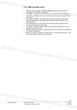
Page 29: ...he high voltage ignition cables separately from the burner housing and other cables while observing the greatest possible distances For example Use an electrically insulating cable channel or distance spacer made from plastic for example see also the Appendix Example for wiring earthing and shielding of the LMV6 Use a 2 pole ignition where possible see drawings below When using a 2 pole ignition t...

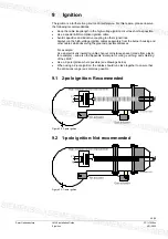
Page 30: ...mportant to have a low impedance at the mechanical connections transitions of the burner housing no insulation material e g no paint Only then will you get a good current flow from the ignition spark back to the ignition transformer resulting in low EM emissions EMC Figure 24 1 pole ignition with low impedance at the burner housing ...

Page 31: ...nections for the burner housing have a high level of impedance e g due to paint this causes multiple poor flows of current from the ignition spark back to the ignition transformer These multiple current flows lead to high EM emissions EMC Figure 25 1 pole ignition with high impedance of the burner housing ...

Page 32: ...pletely separate from all other cables High voltage ignition cable see also chapter Ignition Cable for the flame detectors Together in cable channel 1 for low voltage e g CAN bus cable Together in cable channel 2 for mains voltage e g Cable for ignition transformer Cables for other mains voltage signals e g gas pressure switch and air pressure switch ...

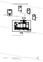
Page 33: ...33 39 Smart Infrastructure LMV6 Installation Guide CC1J7560en 10 Wiring 4 21 2020 Figure 26 Example for wiring earthing and shielding of the LMV6 ...

Page 34: ...nd node The individual bus users are connected in series whereby the respective end nodes are terminated by a bus terminating resistor The LMV6 is a component of the communication line and is looped in between the AZL66 and the SQM4 In this arrangement the AZL66 always assumes the function of a bus end node The required bus terminator is already integrated With the SQM4 the last user becomes the b...

Page 35: ...le type 1 LMV6 system components Figure 28 AGG6 641 Connection Color Wire cross section in mm 24 V DC White 1 25 CAN_H Yellow 0 25 CAN_L Green 0 25 GND Brown 1 25 AGG6 635 cable type 2 LMV6 AZL66 Figure 29 AGG6 635 Connection Color Wire cross section in mm 24 V DC White 0 5 CAN_H Yellow 0 25 CAN_L Green 0 25 GND Brown 0 5 ...

Page 36: ...36 39 Smart Infrastructure LMV6 Installation Guide CC1J7560en 12 Commissioning 4 21 2020 12 Commissioning 12 1 Parallel operation Figure 30 Parallel operation ...

Page 37: ...37 39 Smart Infrastructure LMV6 Installation Guide CC1J7560en 12 Commissioning 4 21 2020 12 2 Variant for parallel operation Figure 31 Variant for parallel operation ...

Page 38: ...ssignment 19 Figure 14 SQM4 connection assignment 19 Figure 15 AGG6 200A5 connection assignment 20 Figure 16 Connection of the protective earth PE functional earth FE with the mounting plate 22 Figure 17 AGG6 500 shielding mechanism optional 22 Figure 18 Earthing and wiring of the LMV6 24 Figure 19 TN S earthing 27 Figure 20 TT earthing 27 Figure 21 Protective earth PE functional earth FE 28 Figur...

Page 39: ... LMV6 Installation Guide CC1J7560en 13 List of figures 4 21 2020 Siemens AG Smart Infrastructure Berliner Ring 23 76437 Rastatt Germany Tel 49 7222 784 2396 www siemens com 2020 Siemens AG Smart Infrastructure Subject to change ...

Reviews: