3
Fläkt Woods
8822 GB 2011.09
Speci
fi
cations are subject to alteration without notice
Installation & maintenance
Control equipment
Use and operation
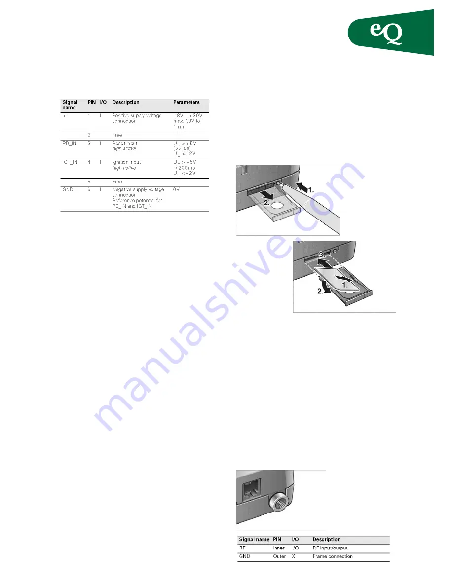
The power supply is implemented by the +- and
the GND wire. To switch the TC35 Terminal on,
proceed as follows:
• Either activate the DTR control line via the RS232
interface
• Or connect IGT_IN to +. This connection has
already been set up in the speci
fi
ed plug-in power
supply unit
Polarity reversal protection
Polarity reversal protection is implemented by
means of a power diode. The diode has a reverse
voltage of 400V.
Overvoltage protection
Overvoltages are suppressed by a Zener diode after
the polarity reversal protection diode.
Fuses
A permanently installed, non-replaceable fuse in
the TC35 Terminal ensures electrical safety in the
event of faults. Connect a fast 1.25A fuse to the
supply line of the positive supply voltage for gene-
ral protection of the Terminal.
SIM card connector
The connector is intended for 3V SIM cards in
accordance with GSM11.12 phase 2 to operate the
Terminal. The SIM card (3V type) must be inserted
in the card holder to put the TC35 Terminal into
operation.
1. Make sure that there is no voltage applied to the
TC35
Terminal.
2. Operate the eject mechanism (yellow pin next to
the card holder) to open the card holder by
pressing it down with a pen, for example.
3. Insert the SIM card in the SIM card holder and
push it back into the housing.
Use and operation
A SIM card holder from Molex with a SIM_IN con-
tact is used. Only when the card holder is inserted
is the switched closed. The card can only be repla-
ced when the GSM engine is in the POWER DOWN
state.
Interference immunity
Electrostatic discharge requirements in accordance
with ETS 300-342-1
Antenna connector FME (male)
A dual band antenna (GSM 900/1800) can be con-
nected to the RF interface. The connection is imple-
mented as a 50
FME (male) coaxial jack.
Antenna connector


