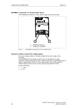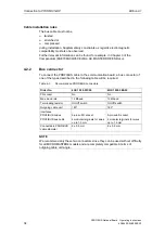
&RQQHFWLRQWR352),%86'3
(GLWLRQ$
PROFIBUS Optional Board Operating instructions
36
6SE6400-5AK00-0BP0
6FUHHQLQJWKHEXVFDEOH(0&SUHFDXWLRQV
The following EMC-related precautions must be taken to ensure interference-free
PROFIBUS-DP operation, particularly in RS-485 data exchange mode:
6FUHHQLQJ
The screen of the PROFIBUS cable must be contacted in the bus connector.
Additional screening is provided via a screen clamp on the bus cable screen which
must make 360° contact with the protective earth. The solid copper core must not
be scored when the insulation is removed from the core ends. It must also be
ensured that the screen of each bus cable is connected to protective earth at both
the cabinet entry point and in the converter housing.
127(DERXWLQVWDOODWLRQ
The bus cables must be internally twisted and screened, and installed separately
from power cables (minimum distance 20 cm). The braided screen and underlying
laminated foil screen (if applicable) must be contacted in a 360°, positive
connection at both ends, i.e. the screen on the bus cable between two converters
must be connected to the converter housing at both ends. The same applies to the
screen of the bus cable between the PROFIBUS-DP master and converter.
Crossovers between bus and power cables must be laid at an angle of 90°.
(TXLSRWHQWLDOERQGLQJ
Differences in potential (e.g. due to different mains supplies) between the
converters and the PROFIBUS-DP master must be avoided.
½
Recommended equipotential bonding cables:
♦
16
mm
2
Cu for equipotential bonding cables up to 200 m long
♦
25
mm
2
Cu for equipotential bonding cables of over 200 m long
½
Equipotential bonding cables must be routed as close as possible to signal
leads, i.e. that the area between the bonding conductor and signal lead is as
small as possible.
½
Equipotential bonding cables must be contacted in a 360° connection with the
earth electrode/PE conductor.
Summary of Contents for Micromaster Profibus
Page 1: ...0 520 67 5 352 86 2SWLRQDO RDUG 2SHUDWLQJ LQVWUXFWLRQV GLWLRQ 8VHU RFXPHQWDWLRQ ...
Page 2: ......
Page 8: ... GLWLRQ PROFIBUS Optional Board Operating instructions 8 6SE6400 5AK00 0BP0 ...
Page 10: ... GLWLRQ PROFIBUS Optional Board Operating instructions 10 6SE6400 5AK00 0BP0 ...
Page 60: ... SSHQGL GLWLRQ PROFIBUS Optional Board Operating instructions 60 6SE6400 5AK00 0BP0 ...
Page 62: ... ORVVDU GLWLRQ PROFIBUS Optional Board Operating instructions 62 6SE6400 5AK00 0BP0 ...
Page 64: ......
Page 65: ......


