background image

(GLWLRQ$

/LQNVWR352),%86'30DVWHU6\VWHPV

PROFIBUS Optional Board    Operating instructions

6SE6400-5AK00-0BP0

45

0,&520$67(5DV'3VODYHZLWKH[WHQGHGIXQFWLRQDOLW\

The extended scope of functions includes:

½

  Acyclical communication with a SIEMENS start-up tool (e.g. STARTER) and

SIMATIC HMI

½

  Optional configuration of process data

½

  Utilization of internode data communication

The MICROMASTER4 with extended functionality is based on an S7-specific
configuring software add-on called the "Slave Object Manager".
After the Slave Object Manager has been installed in STEP 7, the MICROMAS-
TER4 is displayed as a separate folder in the STEP 7 HW Catalog (under the
SIMOVERT folder).

The Slave Object Manager replaces and extends the functionality of the GSD-
based, STEP 7-integrated option.

The Slave Object Manager is an integral component of the following products:

½

  "Drive ES Basic V5.1"

6SW1700-5JA00-1AA0

½

  "Drive ES SIMATIC V5.1"

6SW1700-5JC00-1AA0

½

  "Drive ES PCS7 V5.1"

6SW1700-5JD00-1AA0

(these products require STEP 7 version 5.1 or PCS7 version 5.1.)

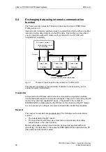
Further information about configuring the data exchange between a
MICROMASTER4 and a SIMATIC S7 can be found in the description of block
package "Drive ES SIMATIC“ or in the online help of the Slave Object Manager.

2SWLRQDOFRQILJXUDWLRQ

Up to four process data, separated according to setpoints and actual values, can
be configured in each telegram.
The data exchange can be optionally configured for all DP masters configured with
STEP 7.

8WLOL]DWLRQRILQWHUQRGHGDWDFRPPXQLFDWLRQ

This mode allows permits slaves to intercommunicate directly, instead of indirectly
via the PROFIBUS-DP master.
Internode communication can be utilized only if the installed PROFIBUS-DP master
supports this functionality. This includes, for example, all S7-CPUs with
"equidistance" ("clocking") capability.

Optional configuration and internode data communication are programmed
completely on the "Configuration" card in the Slave Object Manager. The setpoints
and actual values need only be interconnected correctly in the drive.

6WDQGDUGEORFNVIRUGDWDH[FKDQJHZLWK0,&520$67(5

The "Drive ES SIMATIC“ package contains standard function blocks which
implement the exchange of data between the drive and SIMATIC S7 in accordance
with DRIVEProfile, version 2.0 or 3.0. These blocks make it easier to write the user
program.

Summary of Contents for Micromaster Profibus

Page 1: ...0 520 67 5 352 86 2SWLRQDO RDUG 2SHUDWLQJ LQVWUXFWLRQV GLWLRQ 8VHU RFXPHQWDWLRQ ...

Page 2: ......

Page 3: ...LQVWUXFWLRQV 8VHU RFXPHQWDWLRQ 9DOLG IRU GLWLRQ RQYHUWHU 7 SH ORVHG RRS RQWURO 9HUVLRQ MICROMASTER 4 January 2001 GLWLRQ HVFULSWLRQ HQHUDO HILQLWLRQ RPPXQLFDWLRQ RQQHFWLRQ 6WDUW 8S LQNV WR 0DVWHU 6 VWHPV LDJQRVWLFV DQG 7URXEOHVKRRWLQJ SSHQGL ORVVDU ...

Page 4: ...er this fact shall not constitute an obligation to supply such functions with a new control or when servicing We have checked that the contents of this document correspond to the hardware and software described There may be discrepancies nevertheless and no guarantee can be given that they are completely identical The information contained in this document is reviewed regularly and any necessary c...

Page 5: ...particular problems arise which are not covered sufficiently for the Purchaser s purposes the matter should be referred to the local Siemens Sales Office The contents of this operating manual shall not become part of or modify any prior or existing agreement commitment or relationship The Sales Contract contains the entire obligations of Siemens The warranty contained in the contract between the p...

Page 6: ...out property damage are displayed without a warning triangle Depending on the degree of risk involved safety related information is presented in the following categories 1 5 For the purpose of this documentation and the product warning labels Danger indicates that death severe personal injury or substantial damage to property ZLOO result if proper precautions are not taken 51 1 For the purpose of ...

Page 7: ...tains dangerous voltages and controls potentially dangerous rotating mechanical parts Non compliance with Warnings or failure to follow the instructions contained in this manual can result in loss of life severe personal injury or serious damage to property Only suitably qualified personnel should work on this equipment and only after becoming familiar with all safety notices and maintenance proce...

Page 8: ... GLWLRQ PROFIBUS Optional Board Operating instructions 8 6SE6400 5AK00 0BP0 ...

Page 9: ... 1 Maximum cable lengths 33 4 2 2 Bus connector 34 4 2 3 Bus terminator 35 4 2 4 Removing a bus connector 35 4 2 5 Screening the bus cable EMC precautions 36 5 Starting up the PROFIBUS Board 37 5 1 PROFIBUS address 37 5 2 Communication board parameters 39 6 Links to PROFIBUS DP Master Systems 43 6 1 General 43 6 2 Operation on SIMATIC S5 43 6 3 Operation on SIMATIC S7 44 6 4 Exchanging data using ...

Page 10: ... GLWLRQ PROFIBUS Optional Board Operating instructions 10 6SE6400 5AK00 0BP0 ...

Page 11: ...7 Operating status display for MICROMASTER4 3 Operating status display for PROFIBUS board 8 Latching mechanism 4 PROFIBUS interface 9 Guide 5 Local 24 V connection Fig 1 1 View of communication board 7HFKQLFDO GDWD To display information about the current operating state the communication board has a 3 color LED green orange red Its voltage is supplied via the converter system connector Alternativ...

Page 12: ...ccordance with PROFIDrive Profile version 2 0 or acyclical accessing of parameters data block 47 in accordance with PROFIDrive Profile version 3 0 Acyclical accessing of parameters data block 100 data block 47 for the purpose of exchanging parameter values with a SIMATIC S7 CPU Drive ES SIMATIC function block package Acyclical accessing of parameters for SIMATIC HMI or SIEMENS Drive STARTER tool S...

Page 13: ...ion engineering or visualization systems can operate together with the associated distributed field devices In the context of PROFIBUS master and slave devices are defined as follows Master devices control data traffic on the bus they are also referred to as active nodes A master may transmit messages without prior receipt of an external request provided that it has bus access authorization token ...

Page 14: ...WUDQVPLVVLRQ V VWHP PROFIBUS can be implemented by means of fiber optics for installation in environments susceptible to high levels of radiated emission where electrical isolation is essential or to increase the bus range with high transmission speeds Various fiber types are available to suit different range price and application requirements The following table shows a list of suitable fiber typ...

Page 15: ...S Specification FMS DP PA All normative definitions in relation to the PROFIBUS specification according to EN 50170 Vol 2 0 version 1 0 Order No 0 042 English PROFIBUS DP Expansions includes acyclical communication functions with PROFIBUS DP Extensions to EN 50170 EN 50 170 Vol 2 version 2 0 Order No 2 082 English PROFIBUS Technical Guideline Installation Guidelines for PROFIBUS DP FMS September 1...

Page 16: ... HQHUDO HILQLWLRQ RI 352 86 3 GLWLRQ PROFIBUS Optional Board Operating instructions 16 6SE6400 5AK00 0BP0 ...

Page 17: ...an overview of the PROFIBUS DP communication functions implemented on MICROMASTER4 PROFIBUS communication board MICROMASTER4 Automation Class 1 master S7 S5 and others Configuring Class 2 master DriveES STARTER Operation Class 2 master SIMATIC HMI Acyclic channels Cyclic channels Drive ET200 Internode communication slave Drive ET200 PROFIBUS DP Fig 3 1 PROFIBUS DP data channels on MICROMASTER4 ...

Page 18: ...ading out information about the properties of a parameter such as for example min max limits etc With which PPO type see next page the converter is addressed by the PROFIBUS DP master can be defined in the configuration data for the master when the bus system is started up Which type of PPO is selected depends on the function of the drive in the automation network Process data are always transferr...

Page 19: ...HG DUHDV The useful data structure has been subdivided into the PKW and PZD areas in order to satisfy different functional requirements of the communication system 3DUDPHWHU GDWD DUHD 3 The PKW parameter identifier value telegram section can be used to monitor and or change any parameter in the converter The request response identifier mechanisms required to do this are described in Section 3 4 PK...

Page 20: ... word 2nd word 3rd word 4th word 5th word 6th word 7th word 8th word 9th word 10th word 0D 0D PKW PZD PKE IND PWE Parameter identifier value Process data Parameter identifier Index Parameter value STW ZSW HSW HIW Control word 1 Status word 1 Main setpoint Main actual value Fig 3 3 Parameter process data object optional configuration HIDXOW DVVLJQPHQW RI 3 DP Master Å MICROMASTER4 PZD3 No default a...

Page 21: ...he reaction time of MICROMASTER4 with respect to PZD is approximately 20 milliseconds This represents the period of time between setpoint arrives at DP slave and updated and referencing actual value is made available on PROFIBUS DP The reaction time of the MICROMASTER4 with respect to a parameter modification PKW is approximately 50 milliseconds ...

Page 22: ...n MICROMASTER4 Cyclical data exchange with one class 1 master Use of DATA EXCHANGE and PPO types according to PROFIDrive Profile Acyclical data exchange with the same class 1 master Use of DPV1 functions READ and WRITE The content of the transferred data block corresponds in this case to the structure of the parameter area PKW as defined in the USS specification with data block 100 RU the structur...

Page 23: ...ontrol and inverter pulses are enabled 0 Disable operation Closed loop control and inverter pulses are disabled 4 1 Operating condition 0 Disable ramp function generator Output of RFG is set to 0 fastest possible braking operation converter remains in the ON state 5 1 Enable RFG 0 Stop RFG Setpoint currently supplied by the RFG is frozen 6 1 Enable setpoint Value selected at the RFG input is activ...

Page 24: ... starting lockout state after successful correction and acknowledgement of fault 0 4 1 0 OFF2 command applied See control word bit 1 5 1 0 OFF3 command applied See control word bit 2 6 1 Starting lockout Drive can be restarted only by OFF1 followed by ON 0 No starting lockout 7 1 Alarm is active Alarm see alarm parameter r2110 Drive still in operation 0 8 1 No setpoint act val deviation Setpoint a...

Page 25: ...LJK PWE1 3rd word Parameter value ORZ PWE2 4th word AK PNU Request or response identifier Parameter number Fig 3 4 Structure of parameter area PKW 3DUDPHWHU LGHQWLILHU 3 VW ZRUG The parameter identifier PKE is always a 16 bit value Bits 0 to 10 PNU contain the number of the relevant parameter Bit 11 is reserved Bits 12 to 15 AK contain the request or the response identifier The meaning of the requ...

Page 26: ...ay double word and store in EEPROM 2 5 12 Modify parameter value array word and store in EEPROM 2 4 13 Modify parameter value double word and store in EEPROM 2 14 Modify parameter value word and store in EEPROM 1 7 8 Table 3 4 Response identifier converter master 5HVSRQVH LGHQWLILHU 0HDQLQJ 0 No response 1 Transfer parameter value word 2 Transfer parameter value double word 3 Transfer descriptive ...

Page 27: ...ment cannot be modified Description can never be modified with MICROMASTER4 11 No status as master control Modification request without status as master control see P0927 12 Key word missing 17 Request cannot be processed due to operating state Current converter status is not compatible with the received request 101 Parameter number currently deactivated Dependent on converter status 102 Channel n...

Page 28: ...ex IND when data are transferred cyclically via PPOs The low order byte bits 0 to 7 is not defined in PROFIDrive Profile version 2 0 The low order byte of the parameter index is used on MICROMASTER4 to be able to address additional parameters with a number of 1999 6WUXFWXUH RI 1 IRU DF FOLFDO FRPPXQLFDWLRQ PKE IND PWE1 PWE2 HIGH LOW MICROMASTER4 specific Array subindex 15 8 7 0 Bit 15 PARA PAGE SE...

Page 29: ...ock The function is meaningful only for acyclical data exchange mode The structure of the transferred data block complies with the USS specification The maximum data block size is 206 bytes XQFWLRQ RI 3 5 3 6 The bit for parameter page selection functions as follows If it is set to 1 an offset of 2000 is applied in MICROMASTER4 to the parameter number PNU transferred in the PKW request before it i...

Page 30: ...he response identifier evaluating the parameter number PNU evaluating the parameter index IND if necessary or evaluating the parameter value PWE if necessary The complete request must be sent in one telegram Request telegrams cannot be split The same applies to responses In the case of response telegrams which contain parameter values the drive always returns the momentary parameter value when rep...

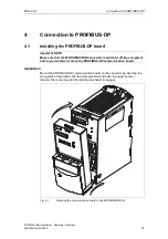
Page 31: ... 67 5 FRQYHUWHU LV VZLWFKHG RII GH HQHUJL HG EHIRUH RX LQVWDOO RU UHPRYH WKH 352 86 3 FRPPXQLFDWLRQ ERDUG QVWDOODWLRQ Mount the PROFIBUS DP communication board on the converter by inserting the two guides at the bottom into the slots provided and push the upper section towards the converter until the latching mechanism engages Fig 4 1 Mounting the communication board on the MICROMASTER4 ...

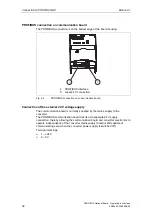
Page 32: ...onnection on communication board RQQHFWLRQ RI WKH H WHUQDO 9 YROWDJH VXSSO The communication board is normally supplied by the mains supply to the converter The PROFIBUS communication board has its own separate 24 V supply connection thereby allowing the communication board and converter electronics to operate independently of the converter mains supply board is still capable of communicating even...

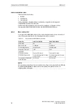
Page 33: ...ed 8 RxD TxD N Receive send data N A A RS 485 9 Not assigned 0D LPXP FDEOH OHQJWKV RS 485 compliant transmission is the transmission mode used most frequently on PROFIBUS DP This requires a twisted screened copper cable with one conductor pair A total of 124 devices can be connected to one PROFIBUS line Up to 32 devices can be interconnected in a linear structure within one bus segment If the conf...

Page 34: ...ion board a bus connector of one of the types described in the following table will be required Table 4 3 Recommended PROFIBUS connectors 2UGHU 1R PG socket No No Max baud rate 12 Mbaud 12 Mbaud Terminating resistor On Off switch On Off switch Outgoing cable unit 180 180 Interfaces PROFIBUS nodes PROFIBUS bus cable 9 pin sub D socket 4 modular terminals for wires up to 1 5 mm 2 9 pin sub D socket ...

Page 35: ...installed on the first and last bus nodes as specified in the diagram below Data cable Data cable VP PIN 6 390 ohms RxD TxD P PIN 3 220 ohms RxD TxD N PIN 8 390 ohms DGND PIN 5 Fig 4 4 Bus terminating network 51 1 A bus segment must always be terminated at both ends by a terminating resistor This is not the case for example if the last slave with bus connector is switched off since the bus connect...

Page 36: ...ely from power cables minimum distance 20 cm The braided screen and underlying laminated foil screen if applicable must be contacted in a 360 positive connection at both ends i e the screen on the bus cable between two converters must be connected to the converter housing at both ends The same applies to the screen of the bus cable between the PROFIBUS DP master and converter Crossovers between bu...

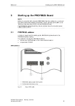
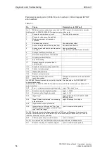
Page 37: ... Advanced Operator Panel AOP into the PROFIBUS board The PROFIBUS optional board may only be installed when the converter power supply is disconnected 352 86 DGGUHVV A minimum requirement for starting up the PROFIBUS optional board is the PROFIBUS address setting Two methods of setting the PROFIBUS address Via the seven DIP switches on the communication board or via parameter P0918 3 VZLWFKHV 1 PR...

Page 38: ...ave a special meaning GGUHVV 0HDQLQJ 0 PROFIBUS address is determined by P0918 1 125 Valid PROFIBUS address 126 127 Invalid PROFIBUS address PSRUWDQW 127 The converter power supply must be switched off before the DIP switch settings are changed if the communication board is already mounted on converter DIP switch setting changes do not take effect until the PROFIBUS has been restarted cold again T...

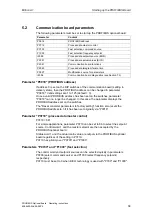
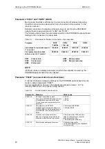
Page 39: ... Valid settings are 1 to 125 default 3 Once a valid PROFIBUS address has been set on the switches parameter P0918 can no longer be changed In this case the parameter displays the PROFIBUS address set on the switches The Reset converter parameters to factory setting function also resets the PROFIBUS address to 3 if it has been set originally via P0918 3DUDPHWHU 3 SURFHVV GDWD PDVWHU FRQWURO P0719 6...

Page 40: ...y the PROFIBUS optional board can be checked 3DUDPHWHU 3 FRPPXQLFDWLRQ ERDUG IXQFWLRQV A number of advanced property settings for the PROFIBUS optional board can be made in indexed parameter P2041 For most applications however the defaults are adequate value 0 The following table shows the property setting options Table 5 2 Communication board functions 3DUDPHWHU 0HDQLQJ 9DOXH UDQJH P2041 00 PPO t...

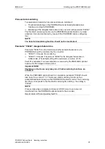
Page 41: ...S should be monitored by the converter P2040 0 means No monitoring P2040 0 means The value of P2040 is the telegram failure time in milliseconds The default setting of the parameter is a value of 0 Fault 07 is activated if no new setpoints are received by the PROFIBUS optional board within the telegram failure period PSRUWDQW 127 6KXWGRZQ RQ IDXOWV FDQ RQO WDNH SODFH LI ERWK PRQLWRULQJ IXQFWLRQV D...

Page 42: ...HWHUV This parameter can be set to define the sources of parameter modifications Bit 0 PROFIBUS DP 0 No 1 Yes Bit 1 BOP 0 No 1 Yes Bit 2 PC converter assembly set USS on the BOP interface 0 No 1 Yes Bit 3 Local RS 485 interface terminal 14 15 and USS 0 No 1 Yes The default setting for all bits is 1 i e parameters can be modified from all sources ...

Page 43: ...ter station You will find the MICROMASTER4 under DP Slaves in the Drives SIMOVERT group For further information about configuring the data exchange between a MICROMASTER4 and a SIMATIC S5 please refer to the description of block package DVA S5 20 352 86 Earlier COM PROFIBUS versions or the latest version COM PROFIBUS V5 1 for Win 95 98 NT 2000 Millenium Order number for version 5 1 order from EWK ...

Page 44: ...STER4 can be operated on a SIMATIC S7 as two different slave types As a DP slave with standard functionality As a DP slave with extended functionality for SIMATIC S7 0 520 67 5 DV 3 VODYH ZLWK VWDQGDUG IXQFWLRQDOLW The MICROMASTER4 with standard functionality is based on the GSD It is displayed directly below the SIMOVERT folder in the STEP 7 HW Catalog The GSD file SIEM80B5 GSD for MICROMASTER4 w...

Page 45: ...figuring the data exchange between a MICROMASTER4 and a SIMATIC S7 can be found in the description of block package Drive ES SIMATIC or in the online help of the Slave Object Manager 2SWLRQDO FRQILJXUDWLRQ Up to four process data separated according to setpoints and actual values can be configured in each telegram The data exchange can be optionally configured for all DP masters configured with ST...

Page 46: ...n PROFIBUS DP The data are generated by the transmitter Publisher and received by one or several receivers Subscribers 7UDQVPLWWHU All input data of a DP slave with internode communication capability constitute transmit data with respect to internode exchanges They can be received by the DP master or by internode capable DP slaves Input data in the context of PROFIBUS DP are data output by the DP ...

Page 47: ... actual values A source destination relationship can be defined for this type of data word e g setpoint 1 is sent by DP master setpoint 2 is sent by an internode capable slave and not by the DP master 1XPEHU RI WUDQVPLW FKDQQHOV A broadcast channel which the DP master and any number of DP slaves can receive i e a maximum of 4 data words on MICROMASTER4 1XPEHU RI UHFHLYH FKDQQHOV Maximum four i e t...

Page 48: ...figuration with two internode transmitters Publishers and one drive as an internode receiver Subscriber PROFIBUS Slave 1 Subscriber MICROMASTER4 Master Slave 1 Inputs Outputs Slave 2 Publisher Inputs Slave 3 Publisher Inputs Inputs actual values Outputs setpoints 1 2 3 4 5 6 7 8 1 2 1 2 3 4 1 2 3 4 1 2 3 4 1 2 3 4 Internodal data Word number Word number Fig 6 2 Example of application of internode ...

Page 49: ...th ProTool The following specific settings for drives must be noted when ProTool is used as the configuring tool Controls Protocol always 6 0 7 6 2WKHU SDUDPHWHUV LHOG 9DOXH Network parameter profile DP Network parameter baud rate optional Communication partner address PROFIBUS address of the drive Communication partner slot subrack don t care 0 9DULDEOHV HQHUDO LQGH FDUG LHOG 9DOXH Name optional ...

Page 50: ...is possible The HMI Variables functions can be used for drives Other functions cannot be used e g Messages or Recipes Individual parameter values can be accessed but access operations to complete arrays descriptions or texts are not possible The diagnostic output on the SIMATIC HMI is limited In the case of accessing difficulties the diagnostic parameters of the communication board i e r2054 03 an...

Page 51: ...pied directly into the appropriate subdirectory If the external master is not compatible to this extent the necessary information must be derived manually from file SIEM80B5 GSD FKDQJLQJ GDWD ZLWK 0 520 67 5 ZLWKRXW VWDQGDUG GDWD EORFNV In cases where block package Drive ES SIMATIC cannot be used the user program must adhere to the system properties with respect to data consistency This means in p...

Page 52: ... LQNV WR 352 86 3 0DVWHU 6 VWHPV GLWLRQ PROFIBUS Optional Board Operating instructions 52 6SE6400 5AK00 0BP0 ...

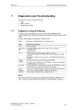
Page 53: ...n Startup and no communication yet with the converter or new communication board configuration after modification of a board parameter If this status is steady then the converter or PROFIBUS optional board is defective orange flashing Communication link to converter has been established No connection to PROFIBUS e g PROFIBUS connector is not inserted or PROFIBUS master disconnected orange on Commu...

Page 54: ...N A704 Cause At least one configured internode transmitter is not yet active or has failed Remedy Activate internode transmitter A705 Cause No actual values received from converter Remedy None fault is in converter A706 Cause PROFIBUS DP communication board Software error Remedy None fault on the PROFIBUS DP communication board for details see diagnostic parameter A710 Cause Converter has detected...

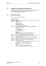
Page 55: ...etpoints and actual values pxxyy decimal p 1 0 PKW configured or not xx Length setpoints yy Length actual values DPSOH 10404 PKW configured 4 setpoints and actual values each 204 No PKW configured 2 setpoints and 4 actual values r2054 02 Number of acyclical links with class 2 master PC OP 0 2 r2054 03 Error number of last unsuccessful parameter access operation via an acyclical link see Table 7 5 ...

Page 56: ...emented 200 201 Modified minimum maximum not reached exceeded Minimum maximum can be further limited in operation No 240 249 Parameter access is incorrectly formatted Error detected on the PROFIBUS DP communication board Additional info in r2054 05 r2054 06 Parameter number or S7 data block number subindex or S7 data block offset 240 Error in variable address no additional info Legal Data block ar...

Page 57: ...g in P2041 03 the PROFIBUS DP communication board attempts to send the following diagnostics to the converter after detecting a software error 3DUDPHWHU 0HDQLQJ r2054 00 65535 Identifier for details of a software error r2054 01 r2054 05 Name of module in which error has been detected ASCII code r2054 06 Code line in which error has been detected r2054 07 r2054 08 Error details ...

Page 58: ... LDJQRVWLFV DQG 7URXEOHVKRRWLQJ GLWLRQ PROFIBUS Optional Board Operating instructions 58 6SE6400 5AK00 0BP0 ...

Page 59: ...Class 3K3 to DIN IEC 721 3 3 in operation Cooling method Natural air cooling Permissible ambient or coolant temperature In operation In storage In transit 10 C to 50 C 14 F to 122 F 25 C to 70 C 13 F to 158 F 25 C to 70 C 13 F to 158 F Permissible humidity rating Relative air humidity 95 in transit and storage 85 in operation condensation not permissible Supply voltage 6 5 V 5 max 300 mA internal ...

Page 60: ... SSHQGL GLWLRQ PROFIBUS Optional Board Operating instructions 60 6SE6400 5AK00 0BP0 ...

Page 61: ... System GSD Device master file HSW Main setpoint HIW Main actual value HMI Human Machine Interface LWL Fiber optic conductor OP Operator Panel OLP Optical Link Plug OLM Optical Link Module PNU Parameter number PWE Parameter value PKW Parameter identifier PZD Process data STW Control word SlaveOM Slave Object Manager TD Text Display ZSW Status word ...

Page 62: ... ORVVDU GLWLRQ PROFIBUS Optional Board Operating instructions 62 6SE6400 5AK00 0BP0 ...

Page 63: ...ual MICROMASTER PROFIBUS Optional Board Suggestions for technical documentation User Documentation URP Name Order number 6SE6400 5AK00 0BP0 Date of Issue Edition A1 Company Service Department Address Phone __________ Fax ________ Should you come across any printing errors when reading this publication please notify us on this sheet Suggestions for improvement are also welcome ...

Page 64: ......

Page 65: ......

Page 66: ...Standard Drives SD Division Postfach 3269 D 91050 Erlangen Federal Republic of Germany Siemens AG 2001 Subject to change without prior notice Siemens Aktiengesellschaft Order No 6SE6400 5AK00 0BP0 Printed in the Federal Republic of Germany 01 01 ...

Reviews: