


© Siemens plc 1999
© Siemens plc 1999
G85139-H1751-U529-D1
G85139-H1751-U529-D1
4/8/99
4/8/99
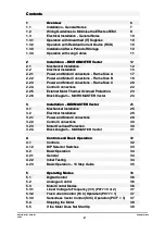
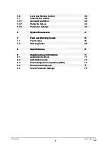
Contents
Contents
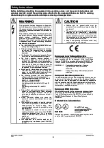
SAFETY INSTRUCTIONS.............................................4
SAFETY INSTRUCTIONS.............................................4
1.
1. OVERVIEW
OVERVIEW .............................................................6
.............................................................6
2.
2. INSTALLATION
INSTALLATION -
- MICROMASTER
MICROMASTER Vector
Vector .........12
.........12
3.
3. INSTALLATION
INSTALLATION -
- MIDIMASTER
MIDIMASTER Vector..............
Vector.............. 25
25
4.
4. CONTROLS
CONTROLS AND
AND BASIC
BASIC OPERATION...............
OPERATION............... 32
32
5.
5. OPERATING
OPERATING MODES...........................................36
MODES...........................................36
6.
6. SYSTEM
SYSTEM PARAMETERS
PARAMETERS .....................................41
.....................................41
7.
7. FAULT
FAULT AND
AND WARNING
WARNING CODES..........................65
CODES..........................65
8.
8. SPECIFICATIONS
SPECIFICATIONS ................................................67
................................................67
9.
9. SUPPLEMENTARY
SUPPLEMENTARY INFORMATION....................73
INFORMATION....................73
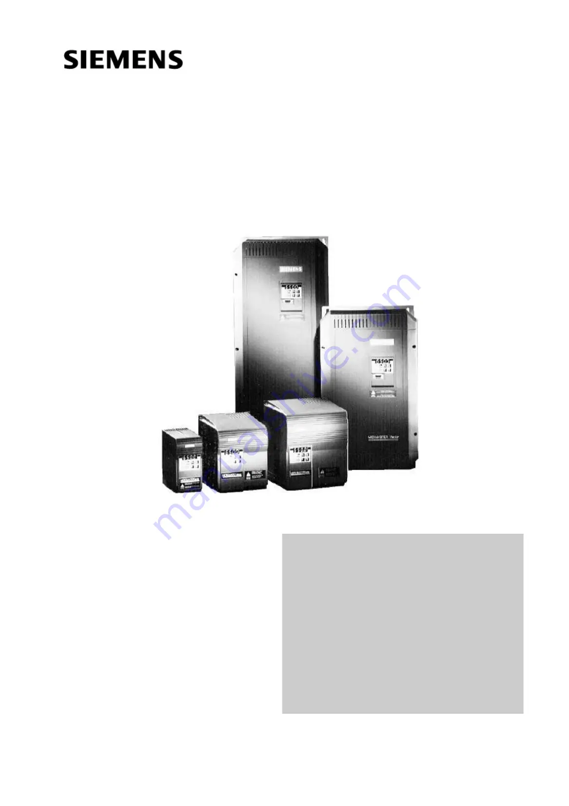
MICROMASTER
MICROMASTER Vector
Vector
MIDIMASTER
MIDIMASTER Vector
Vector
Operating Instructions
Operating Instructions


