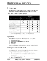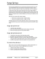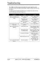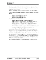
7ML19985CW01
Milltronics ILE-37 – INSTRUCTION MANUAL
Page 5
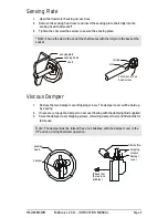
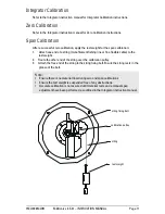
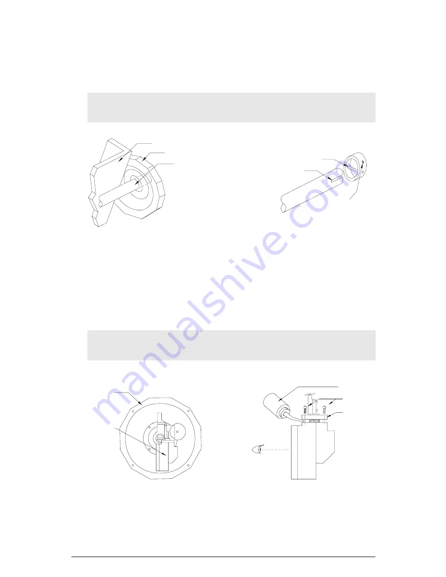
Sensing Plate
1.
Open the flowmeter housing access door.
2.
Remove the sensing head cover and insert the sensing plate shaft fully into the
sensing head shaft socket*.
3.
Tighten the set screw/hex screw to secure the sensing plate.
Viscous Damper
1.
Remove the two damper cover shipping screws. The damper cover will be held up
by a spring.
2.
If necessary, top up the damper to near overflowing with the damping fluid supplied.
3.
Store the damper cover shipping screws, remaining damper fluid, and filler bottle for
future use.
*
Note:
Ensure the slot in the end of the shaft mates with the roll pin in the back of the
socket.
Note:
The damper must be full and free of air bubbles, with the damper cover in the
UP position, during flowmeter operation.
sensingplate
sensing head
shaft
roll pin
slot
set screw or hex
head screw
sensing
head
damper
filler bottle
shipping
screws
damper
cover
(Check that
there are no
bubbles.)
Summary of Contents for milltronics ILE-37
Page 1: ...Instruction Manual September 2003 ILE 37 milltronics ...
Page 4: ...ii ...
Page 25: ...Notes ...
Page 26: ...Notes ...
Page 27: ......

