UM353-1
Factory Configured Options
March 2003
4-1
4.0 FACTORY CONFIGURED OPTIONS
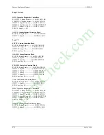
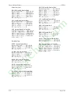
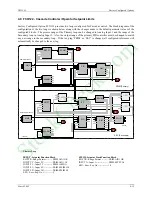
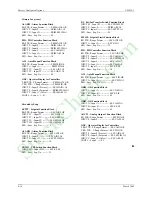
Factory Configured Options provide an easy way to configure a Model 352
Plus
, Model 353, or Model 354. In most
cases a Factory Configured Option (FCO) will provide a complete, functional loop controller, once the proper I/O
connections are made. Changes can be made to an FCO to meet individual requirements. The FCO listings on the
following pages document the parameters that are different than the default values listed in section 3. Some things
to keep in mind when making changes are:
a) All analog signals have been configured for an engineering range of 0.00 to 100.00. In most cases converting
to other engineering units will only require changing the range at the source (e.g. Analog Input function block).
All other blocks (i.e. Controller, Operator Display, Alarm, and Setpoint) that require knowledge of the range
have range pointers that point to the signal source (e.g. Analog Input block) for this information.
b) A number of function blocks have parameters that may be affected by range pointers. The range pointer limits
the setting of parameter values to within -10% to 110% of the range. If a range is changed, the current
parameter values will be changed to the same % within the new range. For example, if the range is 0.0-100.0
and the Alarm 1 Limit setting is 90.0 and the range is changed to 400.0-500.0 the alarm setting will be changed
to 490.0.
c) All controller (ID, PID, PD, PIDAG) outputs have an engineering range of 0.0-100.0 which will be satisfactory
in most cases since outputs normally convert to a 4-20 mA signal to drive a valve 0-100% Open or Closed.
However, when a controller is used in a cascade configuration, the primary controller output must be
configured for the same engineering range as the secondary controller process.
d) FCOs do not change Station parameters or calibration.
e) FCO 0 deletes all loops and set all parameters in the STATN & SECUR function blocks to default values.
Calibration is not affected. As new loops and function blocks are added, parameters will appear at default
values.
StockCheck.com
Summary of Contents for Moore 353
Page 2: ...S t o c k C h e c k c o m ...
Page 14: ...Contents UM353 1 xii March 2003 S t o c k C h e c k c o m ...
Page 24: ...Introduction UM353 1 March 2003 1 10 S t o c k C h e c k c o m ...
Page 152: ...LonWorks Communications UM353 1 March 2003 5 4 S t o c k C h e c k c o m ...
Page 164: ...Network Communications UM353 1 6 12 March 2003 S t o c k C h e c k c o m ...
Page 246: ...Operation UM353 1 March 2003 9 8 S t o c k C h e c k c o m ...
Page 254: ...Controller and System Test UM353 1 March 2003 10 8 S t o c k C h e c k c o m ...
Page 282: ...Circuit Description UM353 1 March 2003 13 4 S t o c k C h e c k c o m ...
Page 298: ...Model Designation and Specifications UM353 1 March 2003 14 16 S t o c k C h e c k c o m ...
Page 302: ...Abbreviations And Acronyms UM353 1 15 2 March 2003 S t o c k C h e c k c o m ...
Page 304: ...Warranty UM353 1 W 2 March 2003 S t o c k C h e c k c o m ...


