UM353-1
Configuration Overview
March 2003
2-3
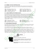
2.5 ETHERNET DATA I/O FUNCTION BLOCKS
These function blocks are available in the quantities indicated within a controller when the optional Ethernet
Network board is installed. These blocks can be selected for use within individual loops but block names are
unique station wide.
AIE
01
-
32
A
nalog
I
nput -
E
thernet (V3.0)
CWE
01-32
C
oil
W
rite -
E
thernet (V3.0)
AOE
01-32
A
nalog
O
utput -
E
thernet (V2.4)
DIE
01-32
D
iscrete
I
nput -
E
thernet (V3.0)
AWE
01-32
A
nalog
W
rite -
E
thernet (V3.0)
DOE
01-32
D
igital
O
utput -
E
thernet (V2.4)
CIE
01-32
C
oil
I
nput -
E
thernet (V3.0)
DWE
01-32
D
igital
W
rite -
E
thernet (V3.0)
2.6 LonWorks REMOTE I/O FUNCTION BLOCKS
These function blocks are available in the quantities indicated within a controller when the optional LonWorks
Remote I/O board is installed. LonWorks is available for use with Models 352P, 353 and 354 controllers. These
blocks can be selected within individual loops, but block names will be unique station wide. This allows LonWorks
network managers that identify variables using the block name within an individual node to be unique. For
example, if LOOP01 uses AIP01 and AIP02 and an AIP block is selected in LOOP02 the name will be AIP03.
Detailed information on the use of LonWorks can be found in Section 5. Model 352P only: Select LonWorks by
setting the Option 3 I/O Jumper.
AIP
01-25
A
nalog
I
nput lev_
P
ercent
DIS
1-6
D
igital
I
nput_
S
tate (V1.3)
AOP
01-25
A
nalog
O
utput lev_
P
ercent
DOD
1-6
D
igital
O
utput lev_
D
iscrete, 16 Channels
DID
1-6
D
igital
I
nput lev_
D
iscrete, 16 Channels
DOS
1-6
D
igital
O
utput_
S
tate (V1.3)
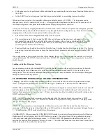
2.7 CONFIGURATION PROCEDURE
Each controller must be configured to perform the desired control strategy. The arrangement of functions and the
numerical data required for a particular control circuit are referred to as the controller configuration. Local and
remote configurations are accommodated.
Local configuration involves the configuration pushbuttons and the pulser knob on the Display Assembly’s
faceplate. Section 9.2 Configuration Mode shows the faceplate and provides brief descriptions of control functions.
Remote configuration requires a personal computer running the i|config™ Graphical Configuration Utility and
either a configuration cable or a Modbus, LIL, or Ethernet network connection. The configuration can be created at
and downloaded from the personal computer. A network connection is made at the controller’s terminals. The
configuration cable plugs into the configuration port in the underside of a 352
Plus
or 353 Display Assembly or into
a 354N DB9 connector. The other end of this cable connects to a personal computer’s serial port or to a modem.
WARNING
Explosion hazard
Explosion can cause death or serious injury.
In a potentially explosive atmosphere, remove power from the
equipment before connecting or disconnecting power, signal
or other circuits.
Comply with all pertinent regulations regarding installation in a
hazardous area.
StockCheck.com
Summary of Contents for Moore 353
Page 2: ...S t o c k C h e c k c o m ...
Page 14: ...Contents UM353 1 xii March 2003 S t o c k C h e c k c o m ...
Page 24: ...Introduction UM353 1 March 2003 1 10 S t o c k C h e c k c o m ...
Page 152: ...LonWorks Communications UM353 1 March 2003 5 4 S t o c k C h e c k c o m ...
Page 164: ...Network Communications UM353 1 6 12 March 2003 S t o c k C h e c k c o m ...
Page 246: ...Operation UM353 1 March 2003 9 8 S t o c k C h e c k c o m ...
Page 254: ...Controller and System Test UM353 1 March 2003 10 8 S t o c k C h e c k c o m ...
Page 282: ...Circuit Description UM353 1 March 2003 13 4 S t o c k C h e c k c o m ...
Page 298: ...Model Designation and Specifications UM353 1 March 2003 14 16 S t o c k C h e c k c o m ...
Page 302: ...Abbreviations And Acronyms UM353 1 15 2 March 2003 S t o c k C h e c k c o m ...
Page 304: ...Warranty UM353 1 W 2 March 2003 S t o c k C h e c k c o m ...

