Maintenance
UM353-1
March
2003
11-20
11.5.6 Ethernet Cable
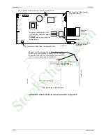
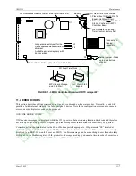
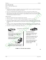
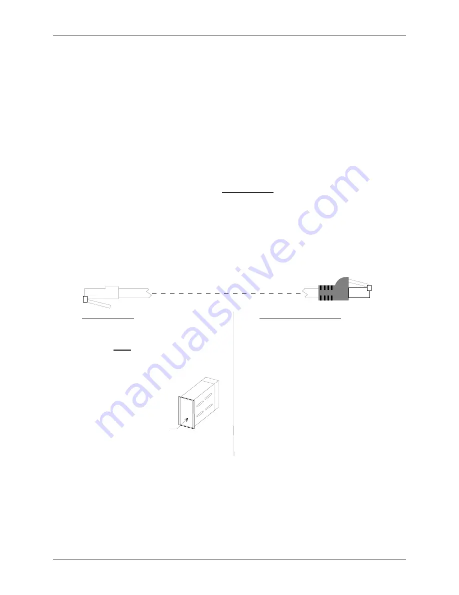
Figure 11-10 shows the Ethernet cable.
REMOVAL
1. At the Ethernet board, press the locking tab on the cable-mounted RJ-45 connector toward the circuit board and
withdraw the connector from the board-mounted connector.
2. Remove the Controller board and I/O Expander board, if present, as described in preceding sections.
3. Inside the case, at the rear panel, press the locking tab on the cable-mounted connector upward and withdraw
the connector from the rear panel mounted connector. A long flat-blade screwdriver may be needed to press the
locking tab upward and release the connector.
INSTALLATION
1. Remove the Controller board and I/O Expander board, if installed.
2. Referring to Figure 11-10, perform the steps under Case Connection to install the cable in the case.
3. Install the I/O Expander board and then MPU Controller board, with the installed Ethernet board, as described
in preceding sections. The Ethernet cable must lie on the floor of the case, between the Expander and Controller
boards.
4. In Figure 11-10, refer to the steps under Ethernet Board Connection to mate the free end of the Ethernet cable
with connector J4 on the Ethernet board. Dress the cable so that it will not interfere with the Display Assembly.
5. Reassemble the controller as described in preceding sections.
Case Connection:
Orient the connector on this end of the cable
as shown above to mate with the RJ-45
connector inside the case, on the connector
socket assembly.
Guide the cable into the case and insert the
cable-mounted connector into the
case-mounted connector.
It may be necessary to gently press on the clear
plastic connector with a long straight-blade
screwdriver to seat the cable-mounted connector.
Ethernet Board Connection:
Install the MPU Controller board with
the attached Ethernet board in the
controller case.
Locate the RJ-45 connector (J4) on the
exposed edge of the Ethernet board.
Note the connector orientation.
Orient the cable-mounted connector
to mate with the board-mounted
connector and insert the cable-
mounted connector.
Supplied Ethernet Cable, 12" (305 mm)
MG
00401a
Insert
Ethernet
Cable
FIGURE 11-10 Ethernet Cable Installation
StockCheck.com
Summary of Contents for Moore 353
Page 2: ...S t o c k C h e c k c o m ...
Page 14: ...Contents UM353 1 xii March 2003 S t o c k C h e c k c o m ...
Page 24: ...Introduction UM353 1 March 2003 1 10 S t o c k C h e c k c o m ...
Page 152: ...LonWorks Communications UM353 1 March 2003 5 4 S t o c k C h e c k c o m ...
Page 164: ...Network Communications UM353 1 6 12 March 2003 S t o c k C h e c k c o m ...
Page 246: ...Operation UM353 1 March 2003 9 8 S t o c k C h e c k c o m ...
Page 254: ...Controller and System Test UM353 1 March 2003 10 8 S t o c k C h e c k c o m ...
Page 282: ...Circuit Description UM353 1 March 2003 13 4 S t o c k C h e c k c o m ...
Page 298: ...Model Designation and Specifications UM353 1 March 2003 14 16 S t o c k C h e c k c o m ...
Page 302: ...Abbreviations And Acronyms UM353 1 15 2 March 2003 S t o c k C h e c k c o m ...
Page 304: ...Warranty UM353 1 W 2 March 2003 S t o c k C h e c k c o m ...

