Model Designation and Specifications
UM353-1
March
2003
14-6
SERVICE PART DESCRIPTION PART
NO.
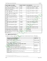
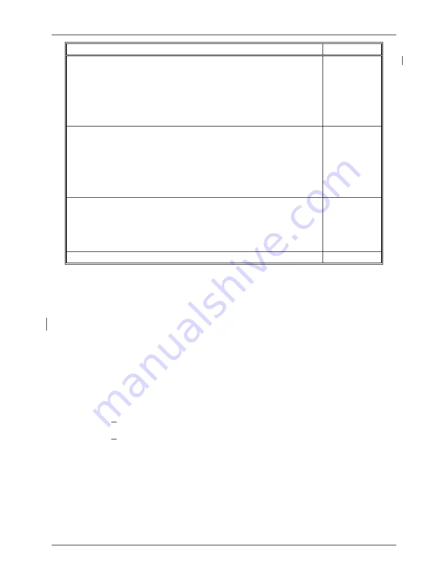
Standard Case with Black Side Entry Connectors, Case Option 2 (Model 353_2...),
includes:
Flange and Case Assembly, qty 1
Expanded Connector Socket Assembly (e.g. 52 terminal capacity), qty 1
Plug-in terminals for H, N, and 3-26
Case Mounting Clip and 8-32 x 1 Fillister Hd. Screw, qty 2 each
Ground Screw, Green, qty 1
Order 16353-133 for plug-in terminals 27-52
Discontinued
Standard Case with Ethernet Connector and Gray or Green Direct Entry Case-
Mounted Connectors, Case Option 4 (Model 353_4...), includes:
Flange and Case Assembly, qty 1
Expanded Connector Socket Assembly with Ethernet Connector and 52 Gray or
Green Case-Mounted Connectors and plug mating connectors
Connector Cover
Case Mounting Clip and 8-32 x 1 Fillister Hd. Screw, qty 2 each
Ground Screw, Green, qty 1
15353-206
Upgrade Kit to Convert Mounting Case option 1 or 2 to option 4 (e.g. Item 136 to
Item 206) includes:
Assembled Connector Socket Assembly, qty 1
Gray or Green Plug-In Connectors for 52 Terminals
Connector Cover
Kit Installation Instruction
16353-230
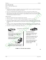
Replacement Ethernet Cable Kit, for an Option 4 case.
15720-368
Notes to Kits:
•
Refer to User’s Manual UM353-1 for accessory part numbers and for servicing a controller.
•
See drawing(s) on previous page for disassembly and item reference numbers.
•
* Identifies a recommended on-hand spare part for the indicated model. Include nameplate information when ordering.
•
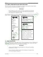
Sample model number: 353 A 4 F 1 N N L T N N A W
•
NS = Not Shown
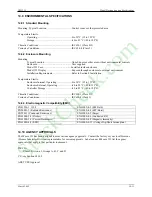
14.4 MECHANICAL SPECIFICATIONS
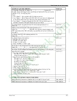
Panel Cutout Dimensions ............................................See Figure 8-3
Controller Dimensions.................................................See Figures 8-4 and 8-5
14.5 POWER INPUT REQUIREMENTS
Voltage Input
Model 353A ..................................................85-264 Vac, 47-63 Hz
AC power ride through time...................25 msec. (minimum)
Model
353D ..................................................24 Vdc, +20%, -15%
Power .......................................................................25 Watts, 40 VA (maximum)
Wire Size, Recommended ...........................................18 AWG (0.96 mm
2
)
Rear Terminals ............................................................H - Hot; N - Neutral; G - Ground, Green Screw
Over-current Protection ...............................................20A maximum fuse or circuit breaker
StockCheck.com
Summary of Contents for Moore 353
Page 2: ...S t o c k C h e c k c o m ...
Page 14: ...Contents UM353 1 xii March 2003 S t o c k C h e c k c o m ...
Page 24: ...Introduction UM353 1 March 2003 1 10 S t o c k C h e c k c o m ...
Page 152: ...LonWorks Communications UM353 1 March 2003 5 4 S t o c k C h e c k c o m ...
Page 164: ...Network Communications UM353 1 6 12 March 2003 S t o c k C h e c k c o m ...
Page 246: ...Operation UM353 1 March 2003 9 8 S t o c k C h e c k c o m ...
Page 254: ...Controller and System Test UM353 1 March 2003 10 8 S t o c k C h e c k c o m ...
Page 282: ...Circuit Description UM353 1 March 2003 13 4 S t o c k C h e c k c o m ...
Page 298: ...Model Designation and Specifications UM353 1 March 2003 14 16 S t o c k C h e c k c o m ...
Page 302: ...Abbreviations And Acronyms UM353 1 15 2 March 2003 S t o c k C h e c k c o m ...
Page 304: ...Warranty UM353 1 W 2 March 2003 S t o c k C h e c k c o m ...

