UM353-1
Function Blocks
March 2003
3-15
3.2.7 AIE_ - Analog Input - Ethernet (V3.0)
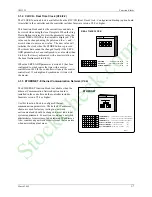
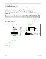
AIE_ function blocks are available when the
optional Ethernet communication board
is installed
in the controller. It enables the controller to read
analog data from other stations over the Ethernet
network.
Up to 32 AIE_ blocks are available. Blocks are
assigned in sequence, controller wide, with each use.
Data can be received as a real floating-point number
and is passed to the block output O1 directly or it
can be obtained as a 16-bit integer. A Floating Point
number can be formatted in one of four methods as
shown in table 1 on the next page. An integer is
converted to floating point as scaled by the MIN
INT & MAX INT and the MINSCALE &
MAXSCALE parameters. Both Unsigned Integer
(Uint) & Signed Integer (Sint) options are available.
See table 2 on the next page.
When A DATA TYP is selected, range limits (see
table 2) are automatically entered. This ensures that
the user-entered integer values fall within the correct range. MIN INT and MAX INT values must be entered
whenever a DATA TYP is changed.
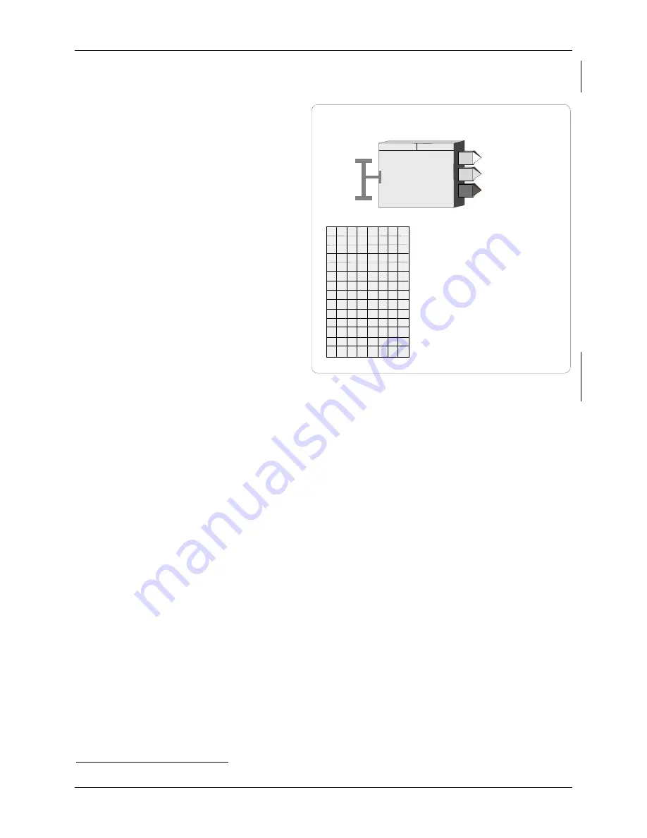
Output OR contains the range scaling for the floating point block output O1. The OR output is a special data type
that includes the MINSCALE, MAXSCALE, DPP, and the ENGUNITS and can be connected to other blocks
having a Range (RG PTR) input. Range scaling information can be automatically obtained from the source of the
data over Ethernet if the device has the scaling information packaged with the data. This is a feature provided by
AOE function blocks from other Siemens MOORE controllers. AOE blocks are defined by using the Modbus
Registers from table 3 below. If this feature is not available, the default setting of the RANGE parameter "MAN"
should be used. In this case, range parameters are entered manually. When the auto range feature is used, the range
in the AIE block may be out of sync for several seconds if on line changes are made to the AOE range.
The IP ADRES parameter is used to configure the IP address of the source device. The MB ADRES parameter
allows a Modbus address to be configured. When connecting to other Siemens MOORE controllers the Modbus
address is set to 1. In some cases, other devices may use a different address or when going through a Modbus
TCP/IP gateway a Modbus network may have multiple devices, each having a unique address. The REG TYP
parameter allows setting the source register as a Holding Register or an Input Register. For many Modbus devices,
this setting does not matter since the device will treat them as identical registers. The DATA TYP parameter will
enable the AIE block to acquire both floating point or integer data. When floating point is selected the controller
will request two consecutive registers starting with the MB REG parameter. The UD RATE parameter configures
the rate at which the block will request data. The P2P setting will update the data at the rate set by the P2P RATE
parameter in the ETHERNET block. The Ct setting will update the data at the cycle time of the controller. The Ct
parameter should normally be used only when the analog input is the process variable in a PID control loop
Output QS indicates the quality of the received data and will go high (1) when the data is bad. This is normally
associated with failure to receive data due to a communication failure or a misconfiguration of the source.
6
Requires Ethernet communications board firmware version 2.0 or later
ANALOG INPUT - ETHERNET
ANALOG INPUT
AIE_
O1
Output
O1
QS
Output
QS
RANGE
(S)
...............................
M
an/
A
uto
(M)
IP AD
d
RES
s
(H)
........ nnn.nnn.nnn.nnn
(192.168.0.0)
MIN
imum
INT
eger
(S)
............ (see table 2)
(*)
MAX
imum
SCALE
(S)
....................... Real
(100.0)
ENG
ineering
UNITS
(S)
....... 6 ASCII Char
(PRCT)
E
th
er
n
et
N
e
tw
or
k
D
ecimal
P
t.
P
osition (preferred)
(S)
............ 0.0.0.0.0.0 0.00
OR
O
utput
R
ange
ETHERNET
M
od
B
us
REG
ister
(H)
........ 00000 - 65535
(00000)
MB AD
d
RES
s
(H)
.......................... 1 - 255
(1)
Modbus
REG
ister
TYPE
(H)
.
InPut
/
Hold
ing
(InPut)
Modbus
DATA
TYP
e
(H)
.....
FP
/
Uint
/
Sint
(FP)
MAX
imum
INT
eger
(S)
........... (see table 2)
(*
)
MIN
imum
SCALE
(S)
........................ Real
(0.0)
BYTE
ORD
er
(S)
........................... 1/2/3/4
(1)
R E
E
P
A
A N G
S
M I N S C A L E
M A X S C A L E
E N G U N I T S
P
P
D
R
I
D
M B
E
R
G
R E
A
S
D
M B
R E G
T Y P
T Y P
D A
T
A
M
I
N
N
I
T
M
I
X
N
A
T
B Y
O R
U D
R
E
U
pdate
RATE
(H)
......................... P2P/Ct
(P2P)
A T
T
E
D
E
StockCheck.com
Summary of Contents for Moore 353
Page 2: ...S t o c k C h e c k c o m ...
Page 14: ...Contents UM353 1 xii March 2003 S t o c k C h e c k c o m ...
Page 24: ...Introduction UM353 1 March 2003 1 10 S t o c k C h e c k c o m ...
Page 152: ...LonWorks Communications UM353 1 March 2003 5 4 S t o c k C h e c k c o m ...
Page 164: ...Network Communications UM353 1 6 12 March 2003 S t o c k C h e c k c o m ...
Page 246: ...Operation UM353 1 March 2003 9 8 S t o c k C h e c k c o m ...
Page 254: ...Controller and System Test UM353 1 March 2003 10 8 S t o c k C h e c k c o m ...
Page 282: ...Circuit Description UM353 1 March 2003 13 4 S t o c k C h e c k c o m ...
Page 298: ...Model Designation and Specifications UM353 1 March 2003 14 16 S t o c k C h e c k c o m ...
Page 302: ...Abbreviations And Acronyms UM353 1 15 2 March 2003 S t o c k C h e c k c o m ...
Page 304: ...Warranty UM353 1 W 2 March 2003 S t o c k C h e c k c o m ...


