UM353-1
Function Blocks
March 2003
3-57
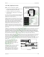
3.2.54 ID - ID Controller
ID
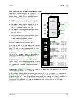
is an integral only controller and one of five controller
types that can be used on a one per loop basis. It uses
external feedback to provide integral action and, therefore,
allows interaction with other function blocks or external
devices, such as pneumatic controllers and shutoff
switches while eliminating windup that can occur with
other controller types. Derivative action is provided when
the parameter TD is non-zero.
When input A is high (1) the controller will operate in the
normal auto mode and when low (0) will cause the output
of the lag function to track the feedback signal. This will
cause the controller output to track the feedback within the
limits. When the controller is switched back to auto, the
value at the input of the lag (GE+FB), if the GE is non-
zero, will cause the output to integrate to a new output at
the TI time constant.
The process range pointer parameter points to a function
block that has range scaling, such as the analog input that
is providing the process variable signal. This enables the
controller to normalize the tuning parameters for the range
of the process input. If this parameter is not configured, the controller will use a range scaling of 0.00 - 100.00.
POWER UP - During a warm or cold start, the output will be initialized to the value of the MINSCALE parameter
and all dynamic states will be initialized to their current input value on the first scan cycle.
t
D S
t
D
D G
S
+ 1
+
+
e
+
-
+
A
t
I S
+ 1
1
O1
F
P
S
BLOCK DIAGRAM
Absolute Value
AE
+
+
+/
-
1
-
A
A
uto
S
etpoint
P
rocess
Abolute Error
O
utput 1
F
eedback
Lead
Lag
Limit
IN
put units
E
ngineering
-3.3 <
O
< 103.3%
scaling
IN
put units
E
ngineering
scaling
scaling
inverse scaling
ID Controller
R
an
G
e
P
oin
T
e
R
FB
GE
ENG UNITS
.
.
P
rocess
ID CONTROLLER
D G
DIR
ect
ACT
ing
(H)
............................... NO/YES
(NO)
O1
O
utput
CONTROLLER
ID
ESN = 000
P
S
F
A
ID
S
etpoint
F
eedback
A
uto
AE
A
bsolute
E
rror
I N P U T
INPUT A
(H)
.....................
loop tag.block tag.output
(null)
E
xec.
S
eq.
N
o.
(H)
........................... 001 to 250
R
T
T I
S C A L E
S C A L E
I
I
I
N
N
N
P
P
P
U
U
U
T
T
T
P
S
F
S
E
N
INPUT F
(H)
.....................
loop tag.block tag.output
(null)
INPUT S
(H)
.....................
loop tag.block tag.output
(null)
INPUT P
(H)
.....................
loop tag.block tag.output
(null)
MIN
imum
SCALE
(H)
................................. Real
(0.0)
D
erivative
G
ain
(S)
....................... 1.00 to 30.00
(10.00)
T
ime -
D
erivative
(S)
............ 0.00 to 100.00 min
(0.00)
T
ime -
I
ntegral
(S)
.................. 0.001 to 4000 m/r
(100.0)
A
P
R
R
an
G
e
P
oin
T
e
R
(S)
...................
loop tag.block tag (null)
A C T
R
I
D
T D
G
M I N
M A X
E N G U N I T S
MAX
imum
SCALE
(H)
............................... Real
(100.0)
ENG
ineering
UNITS
(S)
................6 ASCII Char
(PRCT)
D P P
D
ecimal
P
oint
P
osition (preferred)
(S)
.......... 0.0.0.0.0.0 (0.0)
R
ange
R
OR
O
utput
R
ange
StockCheck.com
Summary of Contents for Moore 353
Page 2: ...S t o c k C h e c k c o m ...
Page 14: ...Contents UM353 1 xii March 2003 S t o c k C h e c k c o m ...
Page 24: ...Introduction UM353 1 March 2003 1 10 S t o c k C h e c k c o m ...
Page 152: ...LonWorks Communications UM353 1 March 2003 5 4 S t o c k C h e c k c o m ...
Page 164: ...Network Communications UM353 1 6 12 March 2003 S t o c k C h e c k c o m ...
Page 246: ...Operation UM353 1 March 2003 9 8 S t o c k C h e c k c o m ...
Page 254: ...Controller and System Test UM353 1 March 2003 10 8 S t o c k C h e c k c o m ...
Page 282: ...Circuit Description UM353 1 March 2003 13 4 S t o c k C h e c k c o m ...
Page 298: ...Model Designation and Specifications UM353 1 March 2003 14 16 S t o c k C h e c k c o m ...
Page 302: ...Abbreviations And Acronyms UM353 1 15 2 March 2003 S t o c k C h e c k c o m ...
Page 304: ...Warranty UM353 1 W 2 March 2003 S t o c k C h e c k c o m ...

