P.T.O.
instabus
®
Technical Manual
Switch/Dimming Actuator
N526E02
5WG1 526–1EB02
June 2015 / Page 1
Product and Applications Description
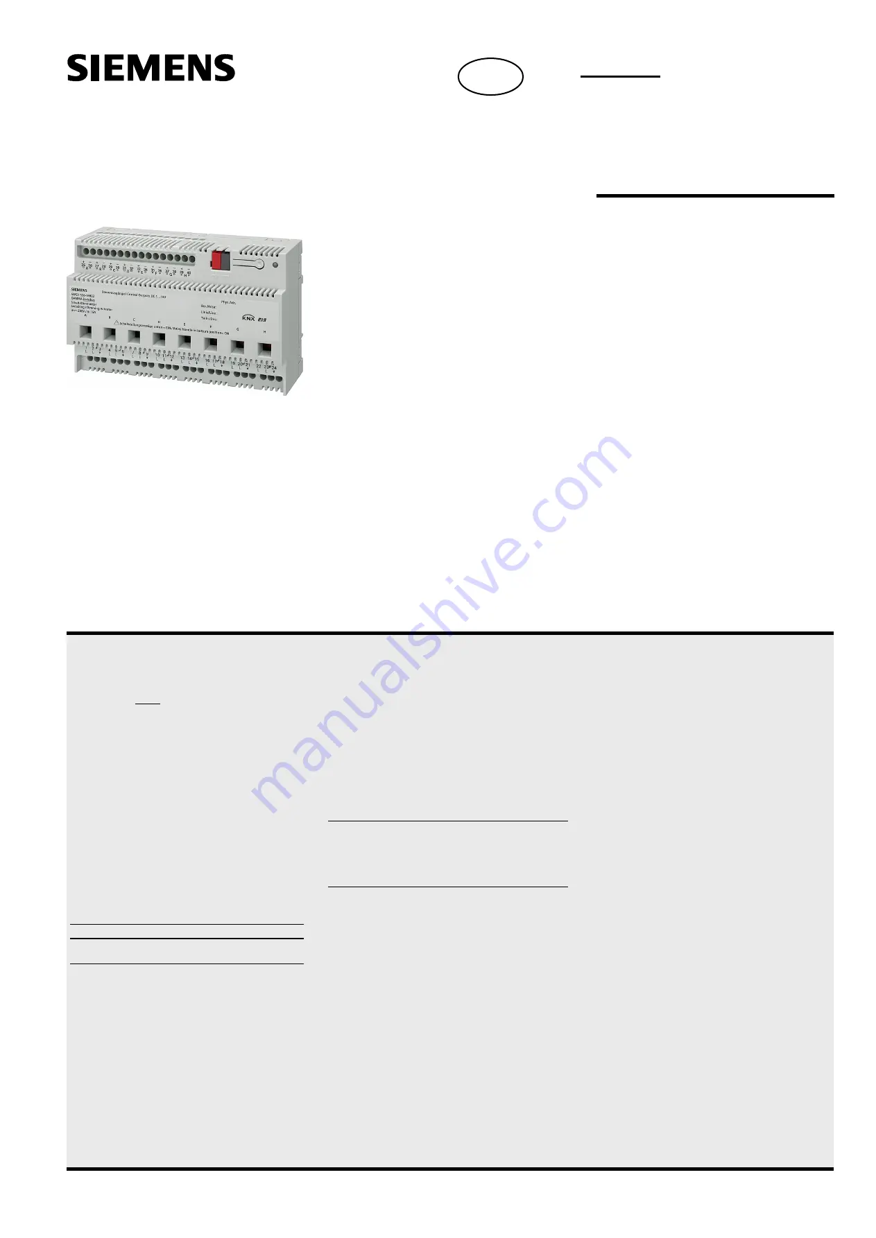
The switching/dimming actuator N 526E02 is a N-
system DIN-rail mounted device for controlling up
to eight groups (channels) of fluorescent lamps via
the DC 1-10 V control terminal of dimmable elec-
tronic ballasts (e.g. ECG-Dynamic-type from Osram).
In addition there is per channel a switching contact
for direct switching on/off of the connected fluores-
cent lamps. This contact can be operated manually
via a slide switch which also indicates the actual
switching state of the channel (when switching
manually as well as when switching via the bus). A
channel is switched on when the slide is in the
lower position.
Different functions can be configured per channel
such as for switching on/off fluorescent lamps,
dimming up / down or setting a particular dimming
level.
With the ETS (Engineering Tool Software) the appli-
cation program is selected, its parameters and ad-
dresses are assigned appropriately and downloaded
into the switching/dimming actuator.
One channel of the N 526E02 switching/dimming
actuator can control several dimmable electronic
ballasts. Their number is limited by the switching
capacity and by the control power. If the on/off
function is not used via the switching contact of the
switching/dimming actuator, the number of control-
lable ECGs is only dependent on the load of the DC
1-10 V control voltage. This might allow to control a
larger number of ECGs (see Technical Specifications
below).
The power supply of the N 526E02 electronics is
provided via the bus (i.e. it requires no additional
power supply). When projecting an installation it
has to be considered that a N 526E02 represents a
double (and for short times even a triple) bus load
and takes up to 30 mA from the bus.
Application Programs
The switching/dimming actuator N 526E02 works
only together with the application program 25 A8
Switch-/ Dimm Actuator 981301. This new applica-
tion program contains several modifications and
new functions (e.g. an integrated 8-bit scene con-
trol). The application program can be loaded from
ETS2 V1.3 onwards.
Technical Specifications
Power supply
·
Bus voltage: DC 29V (Class 2) via the bus line
·
Bus current:: Notice: the device represents at least a
double bus load and takes up to 30 mA from the bus.
Outputs
·
8 outputs (latch relays, potential free contacts)
·
rated voltage: AC 277 V, 50 ... 60 Hz
·
rated current: 20 A, cos phi = 1
·
switching current at AC 277 V: 0,1 ... 20 A, cos phi = 1
·
DC switching current:
- DC 10 ... 30 V: max. 16 A, resistive load
- DC 230 V: max. 0,18 A, resistive load
·
switching characteristic: to be set in parameter list (see
application program description)
Control voltage
·
1 ... 10 V (provided by dimmable ballast)
·
in case of bus voltage failure: 10 V
Control power
·
dimmable electronic ballast:
max 60 units
·
signal amplifier:
max 12 units
CAUTION
There is
no protection of the control circuits against de-
struction by accidental connection to mains voltage!
Operating elements
·
1 learning push button:
for toggling between normal mode/addressing mode
·
8 slide switches for manual operation
(slide in upper position: relay contact open = OFF,
slide in lower position: relay contact closed = ON)
Display elements
·
1 red LED:
for checking the bus voltage and for displaying normal
mode/addressing mode
·
8 slide switches for displaying the switching position per
channel (see above)
Connections
·
load and control circuit, physical:
insulation strip length 8 ... 9 mm
permissible conductor types/cross sections:
-
0,5 ... 4 mm² single core
-
0,5 ... 2,5 mm² flexible conductor
·
load circuit, electrical:
-
plain flexible conductor, min. 1 mm²:
current carrying capacity max. 6 A
-
flexible conductor with terminal pin,
crimped on gas tight, min. 1,5 mm²:
current carrying capacity max. 10 A
-
all other conductors, min. 1,5 mm²:
current carrying capacity max. 16 A
CAUTION
When looping through the L-conductor (connection blocks 1
and 2, 4 and 5, 7 and 8, 10 and 11, 13 and 14, 16 and 17,
19 and 20, 22 and 23), take care that the maximum connec-
tion current of 20 A (as governed by the maximum permissi-
ble printed conductor load) is not exceeded!
·
Bus line:
-
pressure contacts on data-rail
-
screwless bus connection block,
Ø 0,6 ... 0,8 mm single core,
insulation strip length 5 mm
Physical specifications
·
polymer casing
·
N-system DIN-rail mounted device,
width: 8 MU (1 MU = 18 mm)
·
weight: approx. 470 g (29oz)
·
installation: rapid mounting on DIN rail complying with
EN 60715-TH35-7,5
Electromagnetic compatibility
complies with Part 15 of the FCC rules pursuant to the limits
for a Class A digital device
Environmental specifications
• ambient temperature operating: - 5 ... + 45° C (23...113°F)
• maximum ambient temperature range: - 25 ... + 70° C
(-13...158°F)
• relative humidity (non-condensing): 5 % to 93 %
Listings and Certifications
UL listed (E464611)
UL 916, Open Energy Management Equipment
CSA certified
CE marked
In accordance with the EMC guideline (residential and func-
tional buildings) and the low voltage guideline.
KNX / EIB certified
Markings
KNX, EIB, CE, UL
USA


