Configuration
46
Building Technologies
048_DMS_NK8237_ICC_MP4.40_A6V10316241_a_en.doc
Fire Safety & Security Products
06.2011
3.
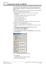
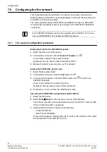
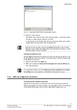
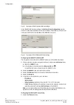
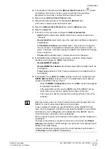
In the
Watchdog Timeout
field, enter the maximum polling delay in seconds.
Configuring the relay output (communication fault)
1.
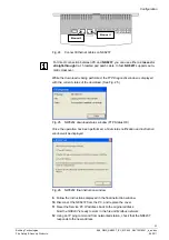
Select the
NK8237
node and expand the subtree.
2.
In the toolbar on the left, select the
Onboard I/O
icon
.
A new Onboard I/O node appears.
3.
Select the new
I/O Onboard
node.
4.
In the toolbar on the left, select the
Relay Output
icon
.
A new Relay Output node appears under the Onboard I/O node.
The relay is configured for communication diagnostics.
By default, the node is named “Relay Output”.
See the onboard output connection on page 14 (X101 connector).
Configuring the inputs (for power supervision or other purposes)
1.
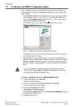
Select the
NK8237
node and expand the subtree.
2.
Select the new
I/O Onboard
node.
3.
In the toolbar on the left, select the
Generic Input
icon
.
A new node appears under the Onboard I/O node.
By default, the new node is named “Generic Input #1”.
4.
If necessary, click one or two more times the
Generic Input
icon
.
New Generic Input nodes appear under the Onboard I/O node.
By default, the new nodes are named “Generic Input #2” and “Generic Input
#3”.
See the onboard input connections on page 15 (X102 connector).
Do not select the
Power Supply Supervision
option for the onboard inputs
even if the signals are used for this supervision purpose. Instead, create the 3
generic inputs and then customise the description texts appropriately.
The Power Supply Supervision configuration option, which globally defines the
input signals, is currently not supported by the NK8237.
Configuring the Time Synchronization mode
1.
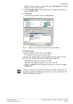
Select the
Modbus Master
node.
2.
Select the
Host
tab.
3.
In the
Time Synchronization
fields, defined the required mode:
If the time synchronization is received from the Modbus master station,
check the
Host enable
checkbox.
If the time synchronization is acquired from the FS20, uncheck the
Host en-
able
checkbox and enter the time of the daily acquisition (HH:MM).
7.7.3
Modbus addresses
The address parameters include:
Modbus devices slave address
These parameters define the Modbus slave addresses of the fire units mapped.
By default, the device address corresponds with the node number in Composer.

