802-9081.9 • INSTALLATION AND OPERATING INSTRUCTIONS • NXPLUS C • Revision 11
119/293
Installation
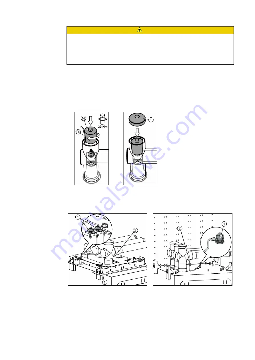
Let excess air out of the screw-type cone with a cable strap while inserting:
➭ Tighten the screw-type cone ⑭ . Pull out the cable strap ⑳ slowly at the same time.
➭ Check whether the cable strap is complete.
➭ To distribute the mounting paste, turn the screw-type cone back a quarter turn.
➭ Tighten the screw-type cone ⑭ with 30 Nm.
➭ Mount the cap ① .
Final work
➭ Mount the earthing cables of the adapters to the switchgear.
➭ Connect all other panels and phases in the same way.
➭ Verify that all unused capacitive taps are earthed.
➭ Mount the busbar support (only for 31.5 kA, see page 122, "Mounting the busbar support").
➭ Install the voltage transformers (option, see page 127, "Installing busbar voltage
transformers").
CAUTION
Disruptive discharges due to air inclusions
Damage to the busbar insulation.
➭ Let excess air out of the screw-type cone with a cable strap while screwing in.
➭ Verify intact condition of the cable strap. If the cable strap was damaged when it was
pulled out, remove the screw-type cone and eliminate the residues of the cable strap.
Earthing connection for circuit-breaker
panel (450 mm) and auxiliary transformer panel
Earthing connection for all other panel types
Fig. 75:
Earthing connection with bolts
Fig. 76:
Earthing connection at welded stud
①
Earthing connection point at the panel
②
Earthing connection point at the adapter


