Installation
120/293
Revision 11 • INSTALLATION AND OPERATING INSTRUCTIONS • NXPLUS C • 802-9081.9
➭ Install the low-voltage compartments (see page 133, "Installing the low-voltage
compartment").
➭ Mount the busbar covers (see page 144, "Mounting the busbar covers").
✔ The installation of the busbar is completed.
Mounting the second busbar level for the 1600/2000/2500 A busbar
For the 1600/2000/2500 A busbar, a second busbar level must be mounted. For this purpose,
mount additional coupling cross adapters and coupling end adapters.
First busbar level
➭ Mount the first busbar level without screw-type cones and caps, see page 115, "Assembling
the 1250 A busbar".
Second busbar level
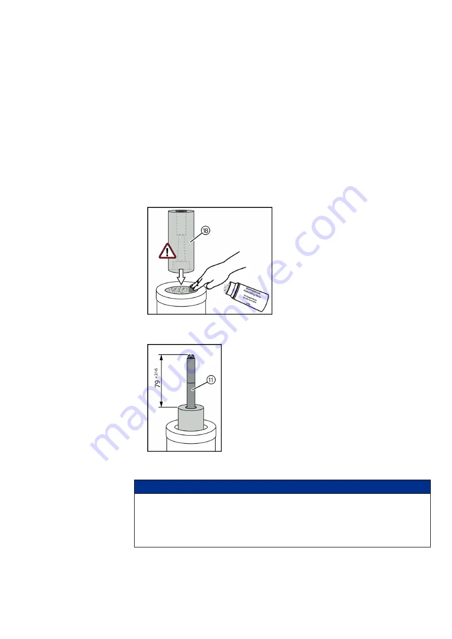
➭ Clean the upper push-on surface of the cross adapter or end adapter, and apply mounting
paste evenly.
➭ Screw the connection stud ⑱ onto the threaded stud ⑪ of the first busbar level (tightening
torque: 50 Nm; insert the hexagon socket spanner fully in the connection stud).
➭ Screw the threaded stud ⑪ into the connection stud as far as it will go (tightening torque:
10 Nm).
Important:
Check reference dimension 79 +2/-6 mm.
➭ Mount the busbar units including coupling cross adapters, coupling end adapters and
busbars in the same way as for the first busbar level.
➭ Push the busbar units on the adapters of the first busbar level.
NOTICE
Flashovers at the coupling adapters
Can damage the switchgear.
The adapter lip must not get out of place or caught. The adapter lip of the coupling adapters
must be in line with the adapters of the first busbar level without any gaps.
➭ Check the seating of the adapter lip and adjust, if required.


