802-9081.9 • INSTALLATION AND OPERATING INSTRUCTIONS • NXPLUS C • Revision 11
133/293
Installation
15.10 Installing the low-voltage compartment
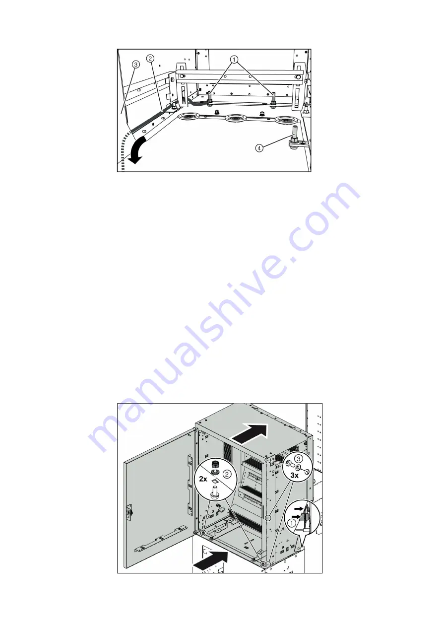
➭ Place the low-voltage compartment onto the frame of the associated panel and push it to
the rear.
The 2 lugs ① at the rear of the low-voltage compartment must be pushed into the cutouts
at the panel. The front of the low-voltage compartment must be in line with the panel front.
➭ Fasten the low-voltage compartment to the frame at 2 positions at the bottom by means of
the bolted joint ② .
➭ Mount all other low-voltage compartments in the same way.
➭ Join each low-voltage compartment with the adjacent low-voltage compartment at
3 positions on the right by means of the bolted joint ③ .
➭ Thread the prefabricated cables of the switching devices through the right-hand opening at
the bottom of the low-voltage compartment.
➭ Connect the 2-pole, 4-pole and 10-pole plugs with the corresponding terminals according to
the circuit diagram (see page 169, "Connecting the STG plug with the VBSTB4 modular
terminal").
➭ Lay the bus wires in wiring ducts and connect them with the corresponding terminals
according to the circuit diagram.
➭ Connect the wires of the current transformers and voltage transformers with the
corresponding terminals according to the circuit diagram.
Fig. 99:
Earthing the switchgear (example)
①
Earthing connection
point
②
Earthing cable
③
Left-hand wiring duct
④
Earthing connection
point extended to the
front for earthing
accessories (do not use)
Fig. 100: Bolting the low-voltage compartment together
①
Lugs
②
Lower bolted joint:
• Locknut M8
• Contact washer 8
• Bolt-and-washer
assembly M8
③
Lateral bolted joint:
• Self-tapping oval head
bolt M5
• Contact washer 5


