Installation
148/293
Revision 11 • INSTALLATION AND OPERATING INSTRUCTIONS • NXPLUS C • 802-9081.9
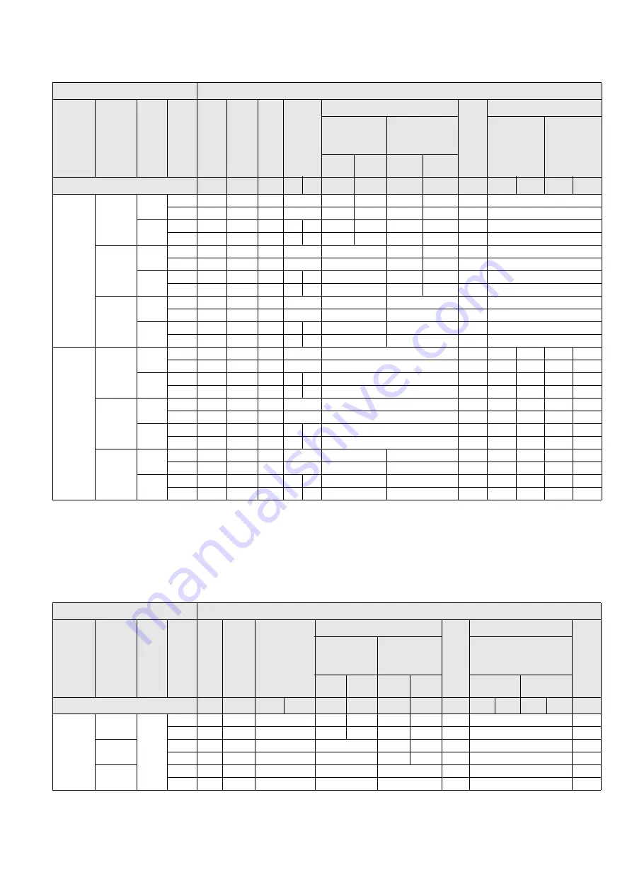
Component table 3
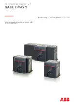
Component table 4
Switchgear panel
Components
Pa
n
el
w
id
th
[m
m
]
Po
si
ti
on
H
ei
g
h
t
of
LV
co
m
p
ar
tm
en
t
Pr
es
su
re
re
lie
f
Su
p
po
rt
in
g
an
g
le
1
C
o
n
n
ec
ti
on
p
la
te
2
C
ov
er
Si
de
w
al
l
3
Angle plate
R
ei
n
fo
rc
in
g
p
la
te
Sealing angle
4
Widht of left-
hand adjacent
panel [mm]
Width of right-
hand adjacent
panel [mm]
Wall-
standing
arrangement
Free-
standing
arrangement
600
900
600
900
Number in exemplary illustration:
①
②
③
④ ⑤
⑥
⑥
⑦
⑦
⑧
⑨
⑩
⑨
⑩
600
Intermedi
ate panel
760
No
96
---
03
05
24
26
25
27
10
---
Yes
---
---
01
05
12
14
13
15
08
---
1160
No
96
84
04
06 07
28
30
29
31
11
---
Yes
---
84
02
06 07
18
20
19
21
09
---
Left end
panel
760
No
96
---
03
05
16
25
27
10
---
Yes
---
---
01
05
16
13
15
08
---
1160
No
96
84
04
06 07
22
29
31
11
---
Yes
--
84
02
06 07
22
19
21
09
---
Right end
panel
760
No
96
---
03
05
---
17
---
---
Yes
---
---
01
05
---
17
---
---
1160
No
96
84
04
06 07
---
23
---
---
Yes
---
84
02
06 07
---
23
---
---
900
Intermedi
ate panel
760
No
---
---
57
05
41
10
97
98
99
100
Yes
---
---
57
05
41
08
97
98
99
100
1160
No
---
85/86
58
39 40
42
11
97
98
99
100
Yes
---
85/86
58
39 40
42
09
97
98
99
100
Left end
panel
760
No
---
---
57
05
41
10
97
---
99
---
Yes
---
---
57
05
41
08
97
---
99
---
1160
No
---
85/86
58
39 40
42
11
97
---
99
---
Yes
---
85/86
58
39 40
42
09
97
---
99
---
Right end
panel
760
No
---
---
36
05
---
43
---
---
98
---
100
Yes
---
---
36
05
---
43
---
---
98
---
100
1160
No
---
85/86
37
39 40
---
44
---
---
98
---
100
Yes
---
85/86
37
39 40
---
44
---
---
98
---
100
1
Only for panel with feeder current ≤ 1000 A.
2
85: For voltage transformers at the busbar in the right-hand adjacent panel.
86: For panel with voltage transformers at the busbar.
3
Mount only one left-hand or right-hand side wall each.
4
Only for left-hand or right-hand adjacent panel with a panel width of 600 mm.
Switchgear panel
Components
Pa
n
el
w
id
th
[m
m
]
Po
si
ti
on
H
ei
g
h
t
of
LV
co
m
p
ar
tm
en
t
Pr
es
su
re
re
lie
f
Su
p
po
rt
in
g
an
g
le
1
C
ov
er
Si
de
w
al
l
2
Angle plate
R
ei
n
fo
rc
in
g
p
la
te
Sealing angle
3
A
n
g
le
Widht of left-
hand adjacent
panel [mm]
Width of right-
hand adjacent
panel [mm]
Type of installation of
the switchgear
600
900
600
900
Wall
Free
Number in exemplary illustration:
①
③
④
⑤
⑥
⑥
⑦
⑦
⑧
⑨
⑩
⑨
⑩
⑪
600
Intermedi
ate panel
760
No
96
124
05
108
110
114
116
10
---
125
Yes
---
101
05
109
112
115
117
106
---
125
Left end
panel
No
96
124
05
113
114
116
10
---
125
Yes
---
101
05
113
115
117
106
---
125
Right end
panel
No
96
124
05
---
118
---
---
125
Yes
---
101
05
---
118
---
---
125


