background image

802-9081.9 • INSTALLATION AND OPERATING INSTRUCTIONS • NXPLUS C • Revision 11

249/293

Operation

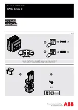
Bus sectionalizer panel with two three-position disconnectors: Earthing the left-hand
busbar system

1

Initial situation

2

➭ Push the interrogation lever downwards

and hold it.

3

➭ Push the left-hand control gate to the left

and hold it (the interrogation lever locks in
lower position. The left-hand actuating
opening for the DISCONNECTING function
opens).

4

➭ Switch the left-hand three-position

disconnector to CLOSED position (insert the
operating lever and turn 90° clockwise).

5

➭ Remove the operating lever (the

interrogation lever and the control gate
return to their initial position).

6

➭ Push the interrogation lever downwards

again and hold it.

7

➭  Push the right-hand control gate to the

right (the interrogation lever locks in lower
position. The right-hand actuating opening
for the READY-TO-EARTH function opens).

8

➭ Switch the right-hand three-position

disconnector to READY-TO-EARTH position
(insert the operating lever and turn 90°
clockwise).

9

➭ Remove the operating lever (the

interrogation lever and the control gate
return to their initial position).

10

➭ To earth the left-hand busbar system, close

the circuit-breaker.

11

➭ Fit a padlock.

Summary of Contents for NXPLUS C

Page 1: ... NXPLUS C Fixed Mounted Circuit Breaker Switchgear up to 24 kV Extendable Single Busbar Metal Enclosed Gas Insulated Medium Voltage Switchgear INSTALLATION AND OPERATING INSTRUCTIONS Order No 802 9081 9 Revision 11 Issue 19 01 2018 ...

Page 2: ...ges of these instructions we reserve the right to modify the specified values and drawings All dimensions are given in mm For further details e g about additional equipment please refer to catalog HA 35 41 Should further information be desired or should particular problems arise which are not covered sufficently by these instructions the matter should be referred to the competent Siemens departmen...

Page 3: ...r 72 10 9 Three position disconnector for circuit breaker disconnector and bus sectionalizer panels 1000 A 76 10 10 Three position switch disconnector for switch disconnector panels ring main panels and circuit breaker panels up to 630 A vacuum contactor panel and metering panel 76 10 11 Endurance classes 77 10 12 Vacuum contactor 78 10 13 Insulating gas 79 11 End of life 80 Installation 81 12 Con...

Page 4: ... Opening the three position switch 193 21 3 Earthing ready to earth with the three position switch 194 21 4 De earthing with the three position switch 194 21 5 Operating the three position switch with motor operating mechanism 195 21 6 Protection tripping of the switch fuse combination 195 21 7 Emergency operation of the three position switch with slow motion mechanism 900 mm panel width 196 22 Wo...

Page 5: ...anism 281 29 6 Visual check of vacuum contactor operating mechanism 282 29 7 Cleaning greasing and lubricating the operating mechanisms 283 29 8 Test operation of the operating mechanisms 283 30 Permissible lubricants 284 31 Extending the switchgear or replacing panels and components 284 Annex 285 32 MCU MH Motor Control Unit Module Housing 285 32 1 Extract from the Technical Description 285 32 2 ...

Page 6: ... as well DANGER Danger Indicates an imminently hazardous situation If this hazardous situation is not avoided death or serious injury will be the consequence Observe the safety instructions WARNING Warning Indicates a potentially hazardous situation If this hazardous situation is not avoided death or serious injury can be the consequence Observe the safety instructions CAUTION Caution Indicates a ...

Page 7: ...rc classification according to IEC 62271 Part 200 personal protective equipment must be worn for operating the switchgear If covers have to be removed to work on switchgear personal protective equipment must be worn for protection against hot gases exhausting in case of internal arc In case of internal arc full personal protection is not provided even if the personal protective equipment is worn I...

Page 8: ...rmware version is installed on the protection devices The latest version of firmware can be obtained from the following website http w3 siemens com smartgrid global en products systems solutions downloads Pages Overview aspx For information to updates for other makes of protection devices please contact the respective manufacturer WARNING High speed moving parts Can cause serious injury Do not rem...

Page 9: ... Qualified personnel in accordance with these instructions are persons who have been instructed by the Switchgear Factory Frankfurt participation in an assembly and installation training with certificate who are familiar with transport installation commissioning maintenance and operation of the product and who have appropriate qualifications for their work Training and instruction or authorization...

Page 10: ...cessible when outgoing feeders are earthed Logical mechanical interlocking Capacitive voltage detecting system to verify safe isolation from supply Earthing of outgoing feeders by means of make proof earthing switch this does not apply to disconnector panels Resistance to internal arcing Pressure resistant design of connection compartments Rear pressure relief duct optional for wall standing arran...

Page 11: ...tand capability option NXPLUS C switchgear can be upgraded for regions at risk from earthquakes For upgrading earthquake qualification testing has been carried out in accordance with the following standards IEC 60068 3 3 Guidance seismic test methods for equipment IEC 60068 2 57 Test Ff Vibration Time history method IEC 60068 2 59 Test Fe Vibration Sine beat method IEEE 693 2005 Recommended Practi...

Page 12: ...panel Bus sectionalizer Metering panel Vacuum contactor panel Ring main panel Vacuum circuit breaker Three position switch disconnector Three position disconnector Capacitive voltage detecting system Current transformer Voltage transformer These components can be connected partially or optionally Cable not included in the scope of supply HV HRC fuse Vacuum contactor ...

Page 13: ...n Cover to cable compartment Capacitive voltage detecting system busbar left side cable feeder right side Control board SIPROTEC bay controller option Low voltage compartment Fig 4 Circuit breaker panel 1000 A Rear pressure relief duct Busbar voltage transformer option Busbar system Three position disconnector Switchgear vessel hermetically welded filled with SF6 gas with bursting disc Circuit bre...

Page 14: ...ght side Control board SIPROTEC bay controller option Low voltage compartment 752 mm for deep cable compartment cover 1120 mm for deep cable compartment cover Fig 6 Circuit breaker panel 2000 A and 2500 A Air guide Busbar system Three position disconnector Switchgear vessel hermetically welded filled with SF6 gas with bursting disc Circuit breaker with vacuum interrupters Ring core current transfo...

Page 15: ...F6 gas with bursting disc Circuit breaker with vacuum interrupters Ring core current transformer option Cable with cable plug for outside cone plug in system Voltage transformer option Voltage transformer disconnector option Cover to cable compartment Capacitive voltage detecting system busbar left side cable feeder right side Control board SIPROTEC bay controller option Low voltage compartment 26...

Page 16: ...lled with SF6 gas with bursting disc Circuit breaker with vacuum interrupters Ring core current transformer option Cable with cable plug for outside cone plug in system Cover to cable compartment Capacitive voltage detecting system busbar left side cable feeder right side Control board SIPROTEC bay controller option Low voltage compartment 2650 mm for high low voltage compartment When only one cab...

Page 17: ... compartment Capacitive voltage detecting system busbar left side cable feeder right side Control board SIPROTEC bay controller option Low voltage compartment Fig 11 Disconnector panel 1250 A Rear pressure relief duct Busbar voltage transformer option Busbar system Three position disconnector Switchgear vessel hermetically welded filled with SF6 gas with bursting disc Ring core current transformer...

Page 18: ...r vessel hermetically welded filled with SF6 gas with bursting disc Cable with cable plug for outside cone plug in system Ring core current transformer option Voltage transformer option Voltage transformer disconnector option Cover to cable compartment Capacitive voltage detecting system busbar left side cable feeder right side Control board SIPROTEC bay controller option Low voltage compartment ...

Page 19: ...position disconnector Switching device vessel hermetically welded filled with SF6 gas with bursting disc Circuit breaker with vacuum interrupters Cable compartment cover Socket for capacitive voltage detecting system busbar left side cable feeder right side Control board SIPROTEC bay controller option Low voltage compartment 2650 mm for high low voltage compartment Fig 14 Bus sectionalizer panel w...

Page 20: ...cting system busbar left side cable feeder right side Control board SIPROTEC bay controller option Low voltage compartment 2650 mm for high low voltage compartment Fig 16 Bus sectionalizer panel with disconnector 2 panel spacings 1250 A Rear pressure relief duct option Busbar system Three position disconnector Switching device vessel hermetically welded filled with SF6 gas with bursting disc Circu...

Page 21: ...Three position switch disconnector Switchgear vessel hermetically welded filled with SF6 gas with bursting disc Fuse assembly with HV HRC fuses Ring core current transformer option Cable with cable plug for outside cone plug in system Cover of cable compartment Capacitive voltage detecting system busbar left side cable feeder right side Control board SIPROTEC bay controller option Low voltage comp...

Page 22: ... filled with SF6 gas with bursting disc Contactor with vacuum interrupters HV HRC fuse assembly with HV HRC fuses Cable with cable plug for outside cone plug in system Ring core current transformer option Voltage transformer disconnector option Cover of cable compartment Socket for capacitive voltage detecting system busbar left side cable feeder right side Control board SIPROTEC bay controller op...

Page 23: ...ug for outside cone plug in system Voltage transformer option Voltage transformer disconnector option Cover to cable compartment Capacitive voltage detecting system busbar left side cable feeder right side Control board Low voltage compartment 2650 mm for high low voltage compartment Fig 21 Metering panel with HV HRC fuses Rear pressure relief duct Busbar system Three position switch disconnector ...

Page 24: ...tor supply voltage fails the closing spring can be charged manually Vacuum interrupters The vacuum interrupter is fixed at the interrupter support The fixed contact is directly connected to the housing The moving contact is firmly connected to the connection bolt and is centrally aligned in the guide A metal bellows forms the vacuum tight connection to the interrupter housing Fig 22 Vacuum interru...

Page 25: ...tactor is latched mechanically in CLOSED position A latch then holds the vacuum contactor in closed position even without auxiliary voltage The vacuum contactor is released electrically either mechanically by means of a pushbutton in the switchgear front or electrically option by a shunt release or undervoltage release The operating mechanism box accommodates all electrical and mechanical componen...

Page 26: ...r operating mechanism Electromechanical interlock 9 4 Three position switch disconnector Designed as a multi chamber switch with the functions DISCONNECTING and EARTHING with the switch positions CLOSED OPEN EARTHED Application Circuit breaker panel 630 A Switch disconnector panel Ring main panel Vacuum contactor panel Metering panel In the following panel types earthing and short circuiting the c...

Page 27: ...aker panel 1000 A 1250 A with increased number of operating cycles 5000 5000 30000 operating cycles option 10000 10000 30000 operating cycles Slow motion mechanism rotary lever mechanism 180 panel width 900 mm Application in the following panel types Circuit breaker panel 2000 A 2500 A Disconnector panel 2000 A 2500 A Bus sectionalizer panel 2000 A 2500 A Position indicator for three position swit...

Page 28: ...echanisms or shunt releases are wired to terminal strips in the low voltage compartment 9 6 Voltage transformers 4MT In NXPLUS C switchgear voltage transformers type 4MT2 and type 4MR can be mounted optionally Common features According to VDE 0414 9 3 and IEC 61869 3 Cast resin insulated Inductive type Arranged outside the primary enclosure switchgear vessel Mounting locations At the busbar 4MT2 P...

Page 29: ...sible with mounted voltage transformer Voltage transformer at the panel connection Switchable through an SF6 insulated disconnecting facility in the switchgear vessel Positions CLOSED and EARTHED Operation of the disconnecting facility from outside through a metal bellows welded in the switchgear vessel Voltage testing of switchgear and cables possible with mounted and earthed voltage transformer ...

Page 30: ...3 8 4 3 8 9 3 10 3 10 5 3 11 3 11 4 3 11 5 3 11 6 3 38 75 GOST 10 3 10 5 3 11 3 42 75 GB 10 3 10 5 3 11 3 17 5 38 95 IEC 12 3 12 4 3 12 47 3 12 5 3 12 8 3 13 2 3 13 4 3 13 8 3 14 4 3 15 3 15 8 3 16 3 17 3 24 50 125 IEC 17 5 3 18 3 19 3 20 3 22 3 23 3 GOST Russian standard GB Chinese standard Secondary data For type Operating voltage V Auxiliary winding Thermal limit current measuring winding Rated...

Page 31: ... enclosure switchgear vessel due to single pole design of cable connection and busbar Free of dielectrically stressed cast resin parts due to design Mounting locations Around the busbar At the panel connection Around the cable Current transformer types Busbar current transformer Inside diameter of transformer 56 mm Usable height for 1250 A busbar 170 mm Usable height for 1600 A 2000 A 2500 A busba...

Page 32: ...ade of cast resin Arrangement of the HV HRC fuse assembly underneath the switching device vessel HV HRC fuse assembly connected to the three position switch disconnector vacuum contactor via welded in bushings and connecting bars Operating voltage max 0 8 kV Rated short duration power frequency withstand voltage winding test 3 kV Rated frequency 50 60 Hz Rated continuous thermal current 1 0 1 2 1 ...

Page 33: ...V HRC fuse links release the striker depending on the temperature and trip the switch disconnector as early as in the overload range of the fuses Impermissible heating of the fuse box can be avoided in this way 9 9 Busbar system The busbar is single pole insulated with silicone rubber Each phase has an earthed layer on the outside screened busbar system This design makes the busbar independent of ...

Page 34: ...g is normally done through a cable connection Insulated cable T plugs without external conductive layer are not permissible as partial discharges can arise very quickly due to the proximity to earthed parts Partial discharges destroy the cable T plug causing an arc between phase and earth The connection of conventional cable sealing ends with elbow adapters e g type AKE is not permissible as this ...

Page 35: ...23 IEC GOST GB DL 300 630 1x SEHDT 23 MUT 23 IEC GOST GB DL nkt cables 25 300 Silicon e 1x CB 12 630 CSA 12 x IEC 25 500 1x CB 17 5 630 CSA 17 5 x GOST GB DL 25 300 1x CB 24 630 CSA 24 x IEC GOST GB DL 185 500 Silicon e 1x CB 24 1250 2 CSA 12 x IEC 95 500 1x CB 24 1250 2 CSA 24 x IEC 400 630 Silicon e 1x CB 36 630 1250 CSA 12 x IEC GOST GB DL 1x CB 36 630 1250 CSA 24 x IEC GOST GB DL 630 1000 Sili...

Page 36: ...12 x IEC GOST GB DL 2x CB 36 630 1250 1x CP 630 M16 CSA 24 x IEC GOST GB DL 630 1000 Silicon e 1x CB 42 1250 3 1x CC 42 2500 3 CSA 12 x IEC 1x CB 42 1250 3 1x CC 42 2500 3 CSA 24 x IEC Tyco Electronics Raychem 25 300 Silicon e 1x RSTI 58xx 1x RSTI CC 58xx RSTI CC 58SAxxxx IEC 1x RSTI 58xx 1x RSTI CC 58xx RSTI CC 68SAxxxx RSTI SA PIN IEC 25 300 Silicon e 1x RSTI 58xx CEE01 1x RSTI CC 58xx CEE01 RST...

Page 37: ...0 1250 IEC GOST GB DL 630 1000 Silicon e 1x CB 42 1250 3 2x CC 42 2500 3 IEC 1x CB 42 1250 3 2x CC 42 2500 3 IEC Tyco Electronics Raychem 25 300 Silicon e 1x RSTI 58xx 2x RSTI CC 58xx IEC 1x RSTI 58xx 2x RSTI CC 58xx IEC 25 300 Silicon e 1x RSTI 58xx CEE01 2x RSTI CC 58xx CEE01 GOST 1x RSTI 58xx CEE01 2x RSTI CC 58xx CEE01 GOST 400 800 Silicon e 1x RSTI 395x 2x RSTI CC 395x IEC 1x RSTI 595x 2x RST...

Page 38: ...25 300 Silicon e 1x CB 12 630 CSA 12 x IEC 25 500 1x CB 17 5 630 CSA 17 5 x GOST GB DL 25 300 1x CB 24 630 CSA 24 x IEC GOST GB DL 185 500 Silicon e 1x CB 24 1250 2 CSA 12 x IEC 95 500 1x CB 24 1250 2 CSA 24 x IEC 400 630 Silicon e 1x CB 36 630 1250 CSA 12 x IEC GOST GB DL 1x CB 36 630 1250 CSA 24 x IEC GOST GB DL 630 1000 Silicon e 1x CB 42 1250 3 CSA 12 x IEC 1x CB 42 1250 3 CSA 24 x IEC Tyco El...

Page 39: ...50 1x CC 36 630 1250 CSA 24 x IEC GOST GB DL 400 630 Silicon e 2x CB 36 630 1250 1x CP 630 M16 CSA 12 x IEC GOST GB DL 2x CB 36 630 1250 1x CP 630 M16 CSA 24 x IEC GOST GB DL 630 1000 Silicon e 1x CB 42 1250 3 1x CC 42 2500 3 CSA 12 x IEC 1x CB 42 1250 3 1x CC 42 2500 3 CSA 24 x IEC Tyco Electronics Raychem 25 300 Silicon e 1x RSTI 58xx 1x RSTI CC 58xx RSTI CC 58SAxxxx IEC 1x RSTI 58xx 1x RSTI CC ...

Page 40: ...250 2x CC 36 630 1250 CSA 24 x IEC GOST GB DL 400 630 Silicon e 3x CB 36 630 1250 2x CP 630 M16 IEC GOST GB DL 3x CB 36 630 1250 2x CP 630 M16 IEC GOST GB DL 630 1000 Silicon e 1x CB 42 1250 3 2x CC 42 2500 3 CSA 12 x IEC 1x CB 42 1250 3 2x CC 42 2500 3 CSA 24 x IEC Tyco Electronics Raychem 25 300 Silicon e 1x RSTI 58xx 2x RSTI CC 58xx RSTI CC 58SAxxxx IEC 1x RSTI 58xx 2x RSTI CC 58xx RSTI CC 68SA...

Page 41: ...x RSTI CC 58xx CEE1 GOST 1x RSTI 58xx CEE1 3x RSTI CC 58xx CEE1 GOST 1 At a continuous current of more than 1150 A cable sealing ends with tin plated nickel plated or silver plated cable lugs are required 2 Observe the actual current and short circuit carrying capacity of the cables and sealing ends Circuit breaker panel 1250 A1 Disconnector panel 1250 A1 Panel spacing 600 mm Make Conductor cross ...

Page 42: ...x IEC 400 630 Silicone 2x CB 36 630 1250 CSA 12 x IEC GOST GB DL 2x CB 36 630 1250 CSA 24 x IEC GOST GB DL Tyco Electronics Raychem 25 300 Silicone 2x RSTI 58xx RSTI CC 58SAxxxx IEC 2x RSTI 58xx RSTI CC 68SAxxxx RSTI SA PIN IEC 25 300 Silicone 2x RSTI 58xx CEE01 RSTI CC 58SAxxxx GOST 2x RSTI 58xx CEE01 RSTI CC 68SAxxxx RSTI SA PIN GOST 400 800 Silicone 2x RSTI 395x RSTI CC 58SAxxxx RSTI SA PIN IEC...

Page 43: ... RSTI 595x 2x RSTI CC 595x RSTI CC 68SAxxxx RSTI SA PIN IEC 400 800 Silicone 2x RSTI 595x CEE01 2x RSTI CC 595x CEE01 RSTI CC 58SAxxxx RSTI SA PIN GOST 2x RSTI 595x CEE01 2x RSTI CC 595x CEE01 RSTI CC 68SAxxxx RSTI SA PIN GOST 3M 50 240 Silicone 4x 93 EE 705 6 2x KU 23 2 IEC GOST GB DL 25 240 4x 93 EE 705 6 2x KU 23 2 IEC GOST GB DL 240 Silicone 2x 93 EE 705 6 2x 93 EE 718 6 IEC GOST GB DL 150 240...

Page 44: ...STI SA PIN IEC 400 800 Silicone 2x RSTI 595x CEE01 4x RSTI CC 595x CEE01 RSTI CC 58SAxxxx RSTI SA PIN GOST 2x RSTI 595x CEE01 4x RSTI CC 595x CEE01 RSTI CC 68SAxxxx RSTI SA PIN GOST Cellpack 50 240 EPDM 2x CTS 630A 24kV 4x CTKS 630A 24kV IEC 25 240 2x CTS 630A 24kV 4x CTKS 630A 24kV IEC 8 cables per panel and phase Nexans Euromold 35 300 EPDM 2x 430TB G 6x 300PB G IEC GOST GB DL 2x K430TB G 6x K30...

Page 45: ...300 Silicon e 1x RSTI 58xx 1x distribution kit RSTI TRF0x RSTI CC 58SAxxxx IEC 1x RSTI 58xx 1x distribution kit RSTI TRF0x RSTI CC 68SAxxxx IEC 25 300 Silicon e 1x RSTI 58xx CEE01 1x distribution kit RSTI TRF0x RSTI CC 58SAxxxx GOST 1x RSTI 58xx CEE01 1x distribution kit RSTI TRF0x RSTI CC 68SAxxxx GOST 3M 50 240 Silicon e 1x 93 EE 705 6 1x distribution kit IEC GOST GB DL 25 240 1x 93 EE 705 6 1x ...

Page 46: ...it IEC GOST 2x CSE A 24630 xx 1x PC 630 3 2x distribution kit IEC GOST Cellpack 50 400 EPDM 2x CTS 630A 24kV 1x CKS 630A 24kV 2x distribution kit IEC 25 300 2x CTS 630A 24kV 1x CKS 630A 24kV 2x distribution kit IEC 50 240 EPDM 1x CTS 630A 24kV 1x CTKS 630A 24kV 2x distribution kit CTKSA IEC 25 240 1x CTS 630A 24kV 1x CTKS 630A 24kV 2x distribution kit CTKSA IEC Ample 25 400 EPDM 1x AQT3 15 630 1x ...

Page 47: ...uired 2 Observe the actual current and short circuit carrying capacity of the cables and sealing ends Circuit breaker panel 630 A 1000 A Switch disconnector panel 630 A Disconnector panel 1000 A Ring main panel 630 A Vacuum contactor panel Circuit breaker panel with top rear cable connection 1250 A 1 Panel spacing 600 mm Make Conductor cross section2 Insulation Cable T plugs Coupling inserts coupl...

Page 48: ...30TB G 1x 300PB G 2x distribution kit MIND IEC GOST GB DL nkt cables 25 120 Silicon e 1x SÜEV10 120CU xxxx CB24 1x SÜEV10 120CU xxxx CC24 CSA 12 x IEC GOST GB DL 150 240 Silicon e 1x SÜEV10 240CU xxxx CB24 1x SÜEV10 240CU xxxx CC24 CSA 12 x IEC GOST GB DL 3 cables per panel and phase Nexans Euromold 35 300 EPDM 1x 430TB G 2x 300PB G 3x distribution kit MIND IEC GOST GB DL Circuit breaker panel 630...

Page 49: ... layer with capacitive measuring point Ample AQT3 15 630 25 400 EPDM with conductive layer 3 core cable PE and XLPE insulated N2YSY Cu and N2XSY Cu or NA2YSY Al and NA2XSY Al Nexans Euromold 430TB G 35 300 EPDM with conductive layer in combination with distribution kit 480TB G 35 300 EPDM with conductive layer in combination with distribution kit nkt cables CB 12 630 25 300 Silicone with conductiv...

Page 50: ...2XSY Cu or NA2YSY Al and NA2XSY Al Nexans Euromold K430TB G 35 300 EPDM with conductive layer in combination with distribution kit K480TB G 35 300 EPDM with conductive layer in combination with distribution kit nkt cables CB 24 630 25 300 Silicone with conductive layer optionally with metal housing in combination with distribution kit CB 24 1250 2 185 500 Silicone with conductive layer in combinat...

Page 51: ...ed ASB and ASBL nkt cables CB 24 630 25 240 Silicone with conductive layer optionally with metal housing in combination with transition sealing end type SÜEV 10 Bar type Bar connection Remark Make Type Conductor material Maximum rated current Solid insulated busbars MGC Moser Glaser Duresca DE Copper 1250 A 2500 A Outer sheath made of polyamide polyamide tube Duresca DG Copper 1250 A 2500 A Outer ...

Page 52: ...for connection of the surge limiter Tyco Electronics Raychem Use of the cable T plug SMOE 63862 for connection of the surge limiter Surge limiters recommended when motors with small starting currents 600 A are connected 9 11 Ready for service indicator Fig 26 Ready for service indicator on the front cover Features Self monitoring easy to read Independent of temperature and external pressure variat...

Page 53: ...erlock prevents the three position switch from being operated while the circuit breaker is closed The switching gate prevents switching straight from CLOSED to READY TO EARTH or from READY TO EARTH to CLOSED as the operating lever must be replaced and re inserted in the OPEN position The control gate of the switching gate of the three position switch can be padlocked in all three switch positions ...

Page 54: ...g in sockets of the plug in voltage indicator or the test socket of the integrated voltage indicator 9 14 Accessories Standard accessories The standard accessories are located in the service flap in the switchgear termination The label Service flap equipment shows the arrangement of the accessories inside the service flap Fig 30 Voltage detecting system via capacitive voltage divider principle Int...

Page 55: ...s Hand crank Operating lever EARTHING READY TO EARTH function Double bit key diameter 3 mm Adhesive label Operating levers for the three position disconnector only for switchgear with panel widths of 600 mm spring operated mechanism spring operated stored energy mechanism Fig 32 Operating lever for DISCONNECTING function black ball handles Fig 33 Operating lever for EARTHING READY TO EARTH functio...

Page 56: ...open the cable compartment cover Other accessories According to the order documents purchase order selection Surge arresters Surge limiters Cable plugs adapter systems Cable plugs HV HRC fuse links Test fuses for mechanical simulation of the striker of HV HRC fuse links in transformer feeders with extension tube for slide lengths 292 mm or 442 mm LRM voltage indicators Units to check the capacitiv...

Page 57: ...802 9081 9 INSTALLATION AND OPERATING INSTRUCTIONS NXPLUS C Revision 11 57 293 Description Holder for operating tools Handle of the cable compartment cover ...

Page 58: ...nce kV 23 321 39 45 60 Rated lightning impulse withstand voltage phase to phase phase to earth open contact gap kV 60 751 95 95 125 across the isolating distance kV 70 851 110 110 145 Rated frequency Hz 50 60 Rated short circuit breaking current kA 31 5 25 Rated short circuit making current kA 63 80 Rated peak withstand current kA 63 80 Rated short time withstand current kA max 31 5 3 s max 25 3 s...

Page 59: ...ents enclosure Busbar compartment Tool based Switching device compartment Non accessible Low voltage compartment Tool based Cable compartment without HV HRC fuses Tool based with HV HRC fuses Interlock controlled and tool based Room height Type of installation for the panel IAC class for rated voltage kV 7 2 12 15 17 5 24 2750 mm Wall standing arrangement IAC A FL 31 5 kA 1 s IAC A FL 25 kA 1 s Fr...

Page 60: ...ure of operating front and side walls IP34D option for switchgear enclosure of operating front and side walls IP54 option for switchgear enclosure of operating front and side walls IP65 for parts under high voltage in switchgear panels without HV HRC fuses Aseismic capacity option NXPLUS C switchgear can be upgraded for regions at risk from earthquakes For upgrading earthquake qualification testin...

Page 61: ...HV HRC fuse links Use only fuse links satisfying the stated operating conditions Use only fuse links whose breaking capacity was tested at least with the maximum system voltage In case of doubt select a suitable HV HRC fuse link together with the manufacturer The three position switch disconnector in the transformer feeder transformer switch was combined with HV HRC fuse links and tested in accord...

Page 62: ... 3 7 2 292 30 098 13 40 X 3 3 3 6 160 4 28 40 3 7 2 292 30 098 13 40 X 50 3 7 2 292 30 098 13 50 X 3 3 3 6 200 4 35 50 3 7 2 292 30 098 13 50 X 63 3 7 2 292 30 099 13 63 X 3 3 3 6 250 4 43 7 63 3 7 2 292 30 099 13 63 X 80 3 7 2 292 30 099 13 80 X 3 3 3 6 315 4 55 1 80 3 7 2 292 30 099 13 80 X 100 3 7 2 292 30 099 13 100 X 3 3 3 6 400 4 70 100 3 7 2 292 30 099 13 100 X 4 4 8 20 4 2 9 6 3 3 7 2 292 ...

Page 63: ...30 101 13 6 3 6 7 2 30 4 2 8 6 3 6 12 292 30 004 13 6 3 X 6 3 3 7 2 292 30 098 13 6 3 X 6 3 6 12 442 30 101 13 6 3 6 7 2 50 4 4 8 10 3 7 2 292 30 098 13 10 X 10 6 12 292 30 004 13 10 X 10 6 12 442 30 101 13 10 16 3 7 2 292 30 098 13 16 X 16 6 12 292 30 004 13 16 X 16 6 12 442 30 101 13 16 6 7 2 75 4 7 2 16 3 7 2 292 30 098 13 16 X 16 6 12 292 30 004 13 16 X 16 6 12 442 30 101 13 16 6 7 2 100 4 9 6...

Page 64: ...5 6 12 442 30 103 43 125 6 7 2 800 5 6 77 125 6 12 442 30 103 43 125 7 6 8 4 20 4 1 5 6 3 6 12 292 30 004 13 6 3 X 6 3 6 12 442 30 101 13 6 3 7 6 8 4 30 4 2 27 5 6 12 292 30 004 13 5 X 6 3 6 12 292 30 004 13 6 3 X 6 3 6 12 442 30 101 13 6 3 7 6 8 4 50 4 3 7 10 6 12 292 30 004 13 10 X 10 6 12 442 30 101 13 10 7 6 8 4 75 4 5 7 16 6 12 292 30 004 13 16 X 16 6 12 442 30 101 13 16 7 6 8 4 100 4 7 6 16 ...

Page 65: ...292 30 012 43 80 X 80 6 12 442 30 102 43 80 8 9 630 4 41 100 6 12 292 30 012 43 100 X 100 6 12 442 30 102 43 100 10 12 20 4 1 15 4 6 12 292 30 004 13 4 X 10 12 30 4 1 7 6 3 6 12 442 30 101 13 6 3 10 12 50 4 2 9 10 6 12 292 30 004 13 10 X 10 6 12 442 30 101 13 10 10 10 17 5 292 30 255 13 10 X 10 10 17 5 442 30 231 13 10 10 10 24 442 30 006 13 10 10 12 75 4 4 3 10 6 12 292 30 004 13 10 X 10 6 12 442...

Page 66: ...12 400 4 23 1 40 6 12 292 30 004 13 40 X 40 6 12 442 30 101 13 40 40 10 17 5 292 30 221 13 40 X 40 10 17 5 442 30 231 13 40 40 10 24 442 30 006 13 40 50 6 12 292 30 004 13 50 X 50 6 12 442 30 101 13 50 50 10 17 5 292 30 221 13 50 X 50 10 17 5 442 30 232 13 50 50 10 24 442 30 014 13 50 10 12 500 4 29 50 6 12 292 30 004 13 50 X 50 6 12 442 30 101 13 50 50 10 17 5 292 30 221 13 50 X 50 10 17 5 442 30...

Page 67: ...3 3 50 10 17 5 442 30 232 13 50 50 10 24 442 30 014 13 50 12 4 13 4 630 4 29 4 63 10 17 5 442 30 232 13 63 63 10 24 442 30 014 13 63 12 4 13 4 800 5 6 37 3 80 10 24 442 30 014 43 80 13 8 20 4 0 8 3 15 10 24 442 30 006 13 3 13 8 30 4 1 25 4 10 24 442 30 006 13 4 13 8 50 4 2 1 6 3 10 17 5 442 30 231 13 6 3 6 3 10 24 442 30 006 13 6 3 13 8 75 4 3 2 6 3 10 17 5 442 30 231 13 6 3 10 10 17 5 442 30 231 ...

Page 68: ... 231 13 25 25 10 24 442 30 006 13 25 14 4 315 4 12 6 20 10 17 5 442 30 231 13 20 20 10 24 442 30 006 13 20 25 10 17 5 442 30 231 13 25 25 10 24 442 30 006 13 25 14 4 400 4 16 1 31 5 10 17 5 442 30 231 13 31 5 31 5 10 24 442 30 006 13 31 5 14 4 500 4 20 1 40 10 17 5 442 30 231 13 40 40 10 24 442 30 006 13 40 14 4 630 4 25 3 50 10 17 5 442 30 232 13 50 50 10 24 442 30 014 13 50 14 4 800 5 6 32 1 63 ...

Page 69: ... 13 31 5 18 19 500 4 16 1 31 5 10 24 442 30 006 13 31 5 40 10 24 442 30 006 13 40 18 19 630 4 20 2 40 10 24 442 30 006 13 40 50 10 24 442 30 006 13 50 63 10 24 442 30 014 43 63 18 19 800 4 5 25 7 50 10 24 442 30 014 13 50 63 10 24 442 30 014 43 63 18 19 1000 5 6 32 1 63 10 24 442 30 014 43 63 18 19 1250 5 6 40 1 80 10 24 442 30 014 43 80 20 23 20 4 0 57 3 15 10 24 442 30 006 13 3 20 23 30 4 0 86 3...

Page 70: ... HV HRC fuse 40 A 50 A 63 A 80 A 100 A 125 A 160 A 200 A 224 A 250 A 3 3 7 2 kV Yes Yes Yes Yes Yes Yes Yes Yes Yes Yes 7 2 12 kV Yes Yes Yes Yes Yes Yes Yes Yes No No 12 23 kV Yes Yes Yes Yes Yes No No No No No HV motors with starting times up to 5 s 2 95 115 135 160 210 415 560 765 860 960 4 85 105 120 145 190 370 500 705 840 960 8 75 95 110 130 170 340 455 640 760 960 16 70 85 95 115 150 300 40...

Page 71: ...50 442 36 30 101 53 50 63 442 45 30 101 53 63 80 442 47 30 102 53 80 100 442 59 30 102 53 100 125 442 74 30 102 53 125 160 442 90 30 103 53 160 200 442 105 30 103 54 200 12 125 442 78 30 469 13 125 12 23 40 442 23 30 006 13 40 50 442 29 30 014 13 50 63 442 36 30 014 43 63 80 442 46 30 014 43 80 100 442 54 30 022 43 100 Voltage transformer HV HRC fuse link Operating voltage Rated current Reference ...

Page 72: ...g cycles 3AH55 Fig 38 Permissible number of operating cycles n as a function of the breaking current Ia r m s value in kA Fig 36 Rating plate on the inside of the low voltage compartment Fig 37 Rating plate at the switchgear vessel Switchgear type Number of operating cycles Serial number Year of manufacture Panel number Technical data Internal arc classification Rated voltage kV 7 2 12 15 17 5 24 ...

Page 73: ...ycles 50 O OPEN operation C CLOSE operation CO CLOSE operation with subsequent OPEN operation at the internal close open time of the vacuum circuit breaker Operating times Component Item designation Duration Unit 3AH55 3AH25 Closing time 75 75 ms Charging time 15 15 s Opening time Shunt release Y1 65 65 ms Additional release 3AX 11 Y2 Y4 Y6 Y7 50 50 ms Arcing time 15 15 ms Break time Shunt release...

Page 74: ...ers are suitable for auto reclosing For DC operation the maximum power consumption is approx 600 W For AC operation the maximum power consumption is approx 750 VA The rated current of the line protection motor operating mechanism is shown in the following table Fuse protection table Line protection of motor operating mechanism for vacuum circuit breaker Rated voltage of operating mechanism Operati...

Page 75: ...y through an electromagnet or deliberately The deliberate tripping of the undervoltage release generally takes place via an NC contact in the tripping circuit or via an NO contact by short circuiting the magnet coil With this type of tripping the short circuit current is limited by the built in resistors Power consumption 20 W or 20 VA Circuit breaker tripping signal When the circuit breaker is tr...

Page 76: ...20 20 20 20 20 Panels with HV HRC fuses tk 1 s tk up to kA 31 5 31 5 31 5 25 25 tk 3 s tk kA 31 5 31 5 31 5 25 25 Rated peak withstand current Panels without HV HRC fuses Ip up to kA 50 63 50 63 50 63 50 63 50 Panels with HV HRC fuses Ip up to kA 80 80 80 63 63 Rated short circuit making current Transformer feeders2 Ima kA 80 80 80 63 63 Ring main feeders Ima up to kA 50 63 50 63 50 63 50 63 50 1 ...

Page 77: ... times rated short circuit breaking current without maintenance C2 IEC 62271 100 Very low probability of restrikes Function Class Standard Property BREAKING M2 IEC 62 271 100 30000 times mechanically with maintenance E2 IEC 62 271 100 30000 times rated normal current 50 times rated short circuit breaking current C2 IEC 62 271 100 Very low probability of restrikes Function Class Standard Property D...

Page 78: ...0265 1 100 times rated mainly active load breaking current I1 1 5 times rated short circuit making current Ima 1 In addition to I1 the class also covers the test currents I2ar I4a I4b I6a and I6b EARTHING M0 E2 IEC 62271 102 IEC 62271 102 1000 times mechanically 5 times rated short circuit making current Ima Function Class Standard Property DISCONNECTING M0 IEC 62271 102 1000 times mechanically LO...

Page 79: ...gas leakage rate is 0 1 per year referred to the absolute gas pressure Rated voltage Operating voltage Power consumption of main coil Rated current of main coil Normal current Smallest possible rated current of the miniature circuit breaker 110 80 Pickup Holding Ua V Umax V Umin V P W Ia A Imax A DC Imin A DC Ia_S A DC 110 121 88 3100 28 18 35 2 25 6 16 120 1 09 1 4 1 0 120 132 96 3100 25 83 32 3 ...

Page 80: ...d fuse slide Silicone rubber The switchgear can be recycled in ecological manner in compliance with existing legislation Auxiliary devices such as short circuit indicators have to be recycled as electronic scrap Any existing batteries have to be recycled professionally As delivered by Siemens the switchgear does not contain hazardous materials as per the Hazardous Material Regulations applicable i...

Page 81: ...cal engineering Untrained or unskilled persons may only enter under the supervision of electricians or persons who have been properly instructed in electrical engineering Outside lockable electrical service locations at places which are not accessible to the public Enclosures of switchgear can only be removed with tools Preparing the switchgear room Observe the following points when preparing the ...

Page 82: ...anel replacement panel extension Control aisle 1400 mm for panel with 600 mm panel width Control aisle 1600 mm for panel with 900 mm panel width Lateral wall distance on left or right 500 mm recommended 125 mm if there are exclusively 600 mm panels Constant loads Vertical single load 8 14 kN1 1 Depending on panel width 600 900 mm Not constant loads Live load 12 kN m2 Minimum distances Control aisl...

Page 83: ...for small room dimensions or spans as well as for few and smaller floor openings Double floor Suitable if neither a cable basement nor sufficient cable ducts can be installed it consists of removable flame retardant floor plates mounted on a supporting structure The supporting floor is about 30 to 80 cm lower depending on the cable routing bending radius DANGER Heavy weight Will cause death seriou...

Page 84: ... Dry Accessible at any time Sufficiently illuminated 12 2 Constructional data of the foundation A suitable foundation can be a false floor a double floor or a reinforced concrete foundation The reinforced concrete floor must be equipped with foundation rails for supporting the panels As for design and construction of the foundation the relevant standards DIN 43661 Fundamentschienen in Innenanlagen...

Page 85: ...loor openings and fixing points Fig 47 Panel with 600 mm panel width Fig 48 Panel with 900 mm panel width Fig 49 Circuit breaker panel with top rear cable connection Left side floor opening for control cables Pressure relief duct option Fixing point Fixing point additionally for resistance against shock vibration earthquakes Floor opening for high voltage cables Cable compartment pressure relief d...

Page 86: ...52 Air insulated metering panel Left hand floor opening for control cables Pressure relief duct Fixing point Fixing point option Floor opening for high voltage cables1 1 Only for auxiliary transformer panels with lateral cable connection Right hand floor opening for control cables only required for zero sequence current transformers in the cable basement Cross member ...

Page 87: ...onal floor bracings The panel and the floor bracings are bolted together onto the foundation rails On panels with a panel width of 900 mm an additional bracing bar must be mounted Fig 53 Floor bracings for panel with a panel width of 600 mm view from the front Fig 54 Floor bracings for panel with a panel width of 900 mm view from the rear Floor bracing at the rear Fixing point Floor bracing at the...

Page 88: ...Distance mm Plug type Distance mm 3M 93 EE 705 6 383 93 EE 718 6 275 Nexans Euromold K 400TB G 383 K 440TB G 383 K 430TB G 383 K 300PB G 278 K 480TB G 383 K 800PB G 273 K 484TB G 383 K 804PB G 273 Südkabel SET 12 24 383 SEHDK 13 1 23 1 273 nkt cables CB xx 630 383 CB xx 630 283 CB 24 1250 2 383 CB 24 1250 2 283 CB 36 630 1250 383 CB 36 630 1250 273 Tyco Electronics Raychem RSTI L56xx 383 RSTI CC L...

Page 89: ...B G 448 K 300PB G 343 K 300PB G 238 K 480TB G 448 K 800PB G 343 K 800PB G 238 K 484TB G 448 K 804PB G 338 K 804PB G 228 K 489TB G 448 K 809PB G 338 K 809PB G 228 Südkabel SET 12 24 448 SEHDK 13 1 23 1 338 SET 12 24 448 SET 12 24 268 SEHDT 13 23 448 SEHDT 13 23 203 nkt cables CB xx 630 448 CB xx 630 268 CB xx 630 448 CC xx 630 348 CC xx 630 248 CB 24 1250 2 448 CB 24 1250 2 268 CB 24 1250 2 448 CC ...

Page 90: ...448 CSE A xx630 xx 276 CSE A xx630 03 448 CSE A xx630 03 268 Cellpack CTS 630A 24kV 448 CTS 630A 24kV 241 CTS 630A 24kV 448 CTKS 630A 24kV 333 CTKS 630A 24kV 218 Ample AQT3 15 630 448 AHT3 15 360 348 Solid insulated bar Moser Glaser 437 Preissinger Ritz Make 1st cable 2nd cable 3rd cable Plug type Distance mm Plug type Distance mm Plug type Distance mm ...

Page 91: ...4PB G 265 K 489TB G 595 K 809PB G 485 K 809PG G 375 K 809PB G 265 Südkabel SET 12 24 595 SEHDK 13 1 23 1 485 SET 12 24 595 SET 12 24 415 SEHDT 13 23 595 SEHDT 13 23 350 nkt cables CB xx 630 595 CB xx 630 415 CB xx 630 235 CB xx 630 595 CC xx 630 495 CC xx 630 395 CB 24 1250 2 595 CB 24 1250 2 415 CB 24 1250 0 235 CB 24 1250 2 595 CB 24 1250 2 495 CC 24 1250 2 395 CC 24 1250 2 295 CB 36 630 1250 59...

Page 92: ...le Plug type Distance mm Plug type Distance mm Plug type Distance mm Plug type Distance mm 1st cable 2nd cable 3rd cable 50 80 mm Deep floor cover Make 1st cable 2nd cable 3rd cable Plug type Distance mm Plug type Distance mm Plug type Distance mm 3M 93 EE 705 6 521 93 EE 718 6 371 93 EE 705 6 521 93 EE 705 6 371 93 EE 715 6 521 93 EE 715 6 371 Nexans Euromold K 400TB G 521 K 400TB G 371 K 430TB 6...

Page 93: ...G 385 K 800PB G 280 K 484TB G 595 K 484PB G 485 K 804PB G 375 K 804PB G 265 Südkabel SET 12 24 595 SEHDK 13 1 23 1 485 SET 12 24 595 SET 12 24 415 SEHDT 13 23 595 SEHDT 13 23 350 nkt cables CBxx 630 595 CBxx 630 415 CCxx 630 235 CBxx 630 595 CCxx 630 495 CCxx 630 395 CB 24 1250 2 595 CB 24 1250 2 415 CB 24 1250 2 235 CB 24 1250 2 595 CC 24 1250 2 495 CC 24 1250 2 395 CC 24 1250 2 295 CB36 630 1250...

Page 94: ...ight approx kg 1 1 Average value depending on the degree to which the panel is equipped mm mm x mm x mm with packing without packing Rail or truck 1 x 450 1100 x 2460 x 1450 900 800 1 x 600 1100 x 2460 x 1450 900 800 1x 600 top rear cable connection 1100 x 2460 x 2100 900 800 1 x 900 1100 x 2460 x 1450 13002 1500 2 Auxiliary transformer panel and air insulated metering panel 12002 1400 Auxiliary t...

Page 95: ...ed on both sides of the panel Transport regulations According to Annex A of the European Agreement Concerning the International Carriage of Dangerous Goods by Road ADR Siemens gas insulated medium voltage switchgear does not belong to the category of dangerous goods in respect of transportation and is exempted from special transport regulations according to ADR Clause 1 1 3 1 b ...

Page 96: ... accessories the delivered switchgear or parts thereof have to be stored before installation a suitable storage room or place has to be selected and prepared Intermediate storage of the transport units In original packing as far as possible Observe the permissible storage temperature from 25 C to 70 C in accordance with the installed secondary devices WARNING Overloading of the storage space Can c...

Page 97: ...y weights as per delivery note Roofed protected against humidity rain water flooding melting water from snow and ice pollution vermin rats mice termites etc and unauthorized access For protection against floor humidity place all crates on planks and square timber After 6 months of storage have the desiccant agent regenerated professionally To do this ask for expert personnel via the regional Sieme...

Page 98: ...artment is an integral part of the panel which means that the protection and control devices with the internal wiring are metal enclosed Reliable earth connections of the frame parts via toothed contact washers or locking washers Inside the panel wires are laid in metal ducts Spatial separation of sensitive signal wires from wires with high interference voltage levels Limitation of switching overv...

Page 99: ...form connection The planning department or site management determines which of the methods will be used taking EMC requirements into account The preceding points should always be taken into account The shield is connected to cables or wires with clamps contacting all around If low demands are placed on EMC it is also possible to connect the shield directly to earth potential combine or twist the s...

Page 100: ...g for transport damages Temporarily open the packing in a weatherproof place to detect hidden damages Stick the PE foil together again and do not remove it totally until reaching the final mounting position in order to keep the switchgear as clean as possible Check the ready for service indicator for SF6 gas see page 105 Checking the ready for service indicator Inform the forwarding agent immediat...

Page 101: ...t be earthed to remove the cable compartment cover Remove the PE film Undo the bolted joints of the cable compartment cover Push the lever of the locking device or of the interlock upwards and hold it DANGER Transport units falling down Can cause death serious injury or damage the transport units The transport units can slip off due to mistakes during transport or while unloading from the lifting ...

Page 102: ...en pallet by means of a fork lift truck Feeder earthed locking device Interlock for cable compartment cover WARNING Heavy weight Can cause death serious injury or property damage Observe all handling instructions in this manual to prevent tipping or dropping of equipment CAUTION Incorrect dimensioning of the lifting tools Can damage the lifting eyes If the lifting eyes are damaged the transport un...

Page 103: ...uter edges and at the joints between the panels Lift one side then the other side of the transport unit with roller crowbars and slowly lower it on the mounting position Apply the roller crowbars only at the corners of the transport units Craning end panels In the end panels there are openings for inserting the crane rods in the side walls Fig 57 Openings for crane rods To insert the crane rods un...

Page 104: ...re installation Place the first i e rearmost transport unit as exactly as possible on its final location and place the second one close to it keeping a small distance so that the units can still be aligned before bolting together Remove packing and transport materials from the place of installation Remove any dirt occurred during transport as extreme cleanliness is required during installation Now...

Page 105: ... the initial position again by hand Remove the front cover To do this undo 2 or 4 bolts at the bottom end of the front cover depending on the panel width and take off the front cover Push the plastic part at the signaling switch downwards with the index finger until the ready for service indicator jumps back to the green area When pushing the plastic part at the signaling switch down from the latc...

Page 106: ...Installation 106 293 Revision 11 INSTALLATION AND OPERATING INSTRUCTIONS NXPLUS C 802 9081 9 Fig 64 Pointer position after operation of the plastic part at the signaling switch ...

Page 107: ...s Isolate Secure against reclosing Verify safe isolation from supply Earth and short circuit Cover or barrier adjacent live parts NOTICE Functional failure due to pollution Pollution or stepping on the switchgear can lead to functional failures during operation Avoid any work that could pollute the switchgear e g sawing filing painting or plastering in the switchgear room etc Do not step on the sw...

Page 108: ...of the auxiliary transformer panel as an end panel Auxiliary transformer panel as left or right end panel To enable working on the lateral cable connection a wall distance of 500 mm must be available Auxiliary transformer panel as right end panel It is recommended to line up from right to left Before being able to line up panels to the left all installation work at the lateral cable connection mus...

Page 109: ...Assembling the busbars If necessary insert spacers between the alignment brackets of the panels The spacers are supplied with the supplementary equipment Fig 66 Mounting the sealing strips Sealing strips Fig 67 Joining the panels Alignment bracket Fixing lug Spacer INFORMATION The cable compartment covers can be coded and the operating mechanism covers are designed specifically for each panel Any ...

Page 110: ... frame Bolt each panel diagonally to the foundation at 2 fixing points at least see page 85 Floor openings and fixing points Use at least 2 fixing bolts M8 or M10 tightening torque M8 30 Nm M10 60 Nm Resistance against shock vibration and earthquakes Install additional floor bracings in every panel see page 87 Resistance against shock vibration and earthquakes option Bolt each panel to the foundat...

Page 111: ...mbly Brush oxidized copper surfaces bright clean and grease them with the supplied mounting paste before connection Use the supplied mounting paste only Tighten all bolted joints with correct torque On all bolted joints execute a torque test with the torque wrench Afterwards mark the bolted joints on the nut with a waterproof pen perform this step only after consultation with the switchgear operat...

Page 112: ...12 293 Revision 11 INSTALLATION AND OPERATING INSTRUCTIONS NXPLUS C 802 9081 9 Phase sequence Mounting plate of low voltage compartment Fig 69 Phase sequence of bushings view from the right Phase L1 Phase L2 Phase L3 ...

Page 113: ...sbar current 1600 2000 and 2500 A Cap Contact half shell Busbar Adjustment component End adapter Busbar insulation Earthing cable Bushing Earthing connection Cross adapter Threaded stud M12 M16 Conical spring washer DIN 6796 12 Hexagon nut ISO 4032 M 12 Screw type cone Coupling end adapter Copper washer galvanized Lock washer Connection stud Coupling cross adapter Adapter lip ...

Page 114: ...LS TS TR RK VS ME EK QK LKLS LKTS L10 L10 L10 L7 L1 L7 L1 L16 L14 LK L3 L3 L2 L1 L11 L6 LS TS L1 L13 L1 L13 L1 L13 L1 L12 L1 L1 L12 L1 L1 L17 LK L1 L2 L1 L2 L1 L1 L1 L1 L9 EB T L10 L10 L10 L7 L1 L7 L1 L14 aME L6 L6 L6 Busbar L1 L2 L3 L4 L5 L6 L7 L8 L9 L10 L11 L12 L13 L14 L15 L16 L17 Length mm 236 281 326 391 436 456 541 566 581 586 626 636 681 716 736 886 981 Reference dimension K1 mm 250 2 295 2 ...

Page 115: ... Check reference dimension 79 2 6 mm Brush oxidized copper surfaces busbar ends and bushings Clean the push on surfaces of the busbars gray surfaces cast resin cones and outside cones of the bushings with a lint free wiping cloth and mounting paste Apply mounting paste to the lower and lateral push on surfaces of the end adapters and cross adapters Apply mounting paste to the push on surfaces gray...

Page 116: ...ctory Switchgear with a busbar current 1600 A Air insulated metering panel If required install the current transformers together with the busbar see page 124 Installing current transformers on the busbar Pre assembled current transformers In case of pre assembled current transformers the bolted joint of the clamping bracket must be undone before mounting the busbar units If required pull the curre...

Page 117: ...ns until the complete busbar run is loosely plugged on the bushings NOTICE Pollution through abrasion Can lead to flashovers and damage the switchgear Abrasion can be produced by canting of the busbar units when pushing them onto the bushings Do not cant busbar units Push busbar units carefully and slowly onto the bushings NOTICE Damage to the end adapters or cross adapters caused by the threaded ...

Page 118: ... spring washer camber upwards and the hexagon nut M12 tightening torque 50 Nm Version B Bolt the threaded stud together with the tin plated copper washer the lock washer and the hexagon nut M12 tightening torque 50 Nm Inserting the screw type cone Apply mounting paste to the screw type cone and the upper push on surface of the cross adapter or end adapter Busbar level Busbar 1250 A 1600 2000 2500 ...

Page 119: ...ount the busbar support only for 31 5 kA see page 122 Mounting the busbar support Install the voltage transformers option see page 127 Installing busbar voltage transformers CAUTION Disruptive discharges due to air inclusions Damage to the busbar insulation Let excess air out of the screw type cone with a cable strap while screwing in Verify intact condition of the cable strap If the cable strap w...

Page 120: ... surface of the cross adapter or end adapter and apply mounting paste evenly Screw the connection stud onto the threaded stud of the first busbar level tightening torque 50 Nm insert the hexagon socket spanner fully in the connection stud Screw the threaded stud into the connection stud as far as it will go tightening torque 10 Nm Important Check reference dimension 79 2 6 mm Mount the busbar unit...

Page 121: ...third busbar level does not extend into an adjacent panel First and second busbar level Mount the first and second busbar level see page 120 Mounting the second busbar level for the 1600 2000 2500 A busbar Do not mount screw type cones and caps on the adapters of the bus sectionalizer panel Third busbar level Mount the coupling adapters of the third busbar level analogously to the second busbar le...

Page 122: ...A design Mount the busbar support at the upper busbar level according to the enclosed installation instructions Do not mount the busbar support On bus sectionalizer panels On right hand end panels On panels with busbar current transformers Circuit breaker panel 450 mm and auxiliary transformer panel Fig 79 Busbar support in the auxiliary transformer panel All other panel types Fig 80 Busbar suppor...

Page 123: ...ort and the switchgear vessel or transformer mounting plate Fig 81 Busbar support for 1600 A 2000 A 2500 A with earthing connection points Busbar support Earthing connection point at the busbar support Earthing connection point at the switching device vessel Fig 82 Mounting the busbar support Hexagon head bolt M10x75 Conical spring washer Washer Cable clamp upper part Distance sleeve Cable clamp l...

Page 124: ...brackets together at the top Wire routing Air insulated metering panel only Lead the connecting wires of the current transformers laterally into the operating mechanism compartment and into the low voltage compartment through the right wiring duct Fig 83 Installing the current transformers busbar current 1250 A Hexagon nut M8 2x Flat washer 8 2x Bolt M8x35 Current transformer Clamping bracket 2x B...

Page 125: ...sbar current transformers 1600 A Cut the felt strips to size and stick 2 of them at the bottom and 1 of them on top of the current transformers Place the current transformer mounting plate onto the current transformers and tighten the nuts Mount the current transformers on the switchgear together with the current transformer mounting plate While installing the current transformers observe the dire...

Page 126: ...te to stabilize the current transformers and tighten the nuts Wire routing Lead the secondary leads from the instrument transformers into the low voltage compartment and connect Fig 86 Cable routing into the low voltage compartment Secondary leads Vertical wiring duct only for secondary leads with steel tube Cutout ...

Page 127: ...ansformers mounted on 1250 A busbar Fig 88 Voltage transformers with lower voltage transformer frame Fig 89 Voltage transformer mounted on the busbar view from the front Voltage transformer Centering nut tightening torque 10 Nm Storage box Hexagon nut M12 tightening torque 50 Nm Voltage transformer frame Conical spring washer Nut and washer assembly M8 bolt M6 with plain washer1 Contact half shell...

Page 128: ...the switchgear Other panel types The threaded studs on the switchgear vessel must fit into the holes of the frame feet Depending on the panel type fasten the voltage transformer frame using nut and washer assemblies or bolts INFORMATION To mount the voltage transformer on the busbar the caps and screw type cones of the busbar are not required Mount the busbar according to the installation instruct...

Page 129: ...busbar insulation can damage the switchgear While installing the voltage transformer let excess air out of the adapter with a cable strap Verify intact condition of the cable strap If the cable strap was damaged when it was pulled out remove the voltage transformer and eliminate the residues of the cable strap INFORMATION To be able to close the busbar in a surge proof way again e g to remove a de...

Page 130: ... the voltage transformer again and verify that no residuals of the cable strap remain in the end adapter cross adapter The voltage transformer must be correctly seated on its bolted joints Fasten the 3 voltage transformers with 4 bolt and washer assemblies and washers each tightening torque 20 Nm Connecting secondary leads Secondary leads are not pre assembled on all voltage transformer types Conn...

Page 131: ... position switch to CLOSED position Connect a voltmeter to the outgoing cable of the voltage transformer and set the mV range Apply 15 to 20 V DC to L1 L2 L3 to earth with the battery and observe the voltmeter If the pointer moves a little bit the voltage transformer connection is in good order Fig 96 Cable routing into the low voltage compartment Secondary leads Vertical wiring duct only for seco...

Page 132: ...and materials of the earthing conductors are specified in the DIN VDE 0101 IEC 61936 1 standard or in the relevant country specific standards The diameter of the earthing cable must be at least 70 mm2 Connect the earthing busbar of the two end panels to the substation earthing system through one of the earthing connection points bolt M12 In addition earth every fifth panel Lay the earthing cable t...

Page 133: ...ed cables of the switching devices through the right hand opening at the bottom of the low voltage compartment Connect the 2 pole 4 pole and 10 pole plugs with the corresponding terminals according to the circuit diagram see page 169 Connecting the STG plug with the VBSTB4 modular terminal Lay the bus wires in wiring ducts and connect them with the corresponding terminals according to the circuit ...

Page 134: ...mbled Install the switchgear termination see page 143 Installing the switchgear termination Install the horizontal pressure relief duct Design option Panel width mm Busbar current depending on the panel position1 1 Independently from the panel position the panel types LS LLK 2000 A 2500 A EB and aME are always equipped with ventilation Left end panel Intermediate panel Right end panel Standard wit...

Page 135: ... Evacuation duct termination expanded metal 260 mm Angle Type designation Angle Dimensions Evacuation duct angle vertical 45 Evacuation duct angle horizontal 45 Supports Type designation Illustration Fixing lugs for evacuation duct Fixing bracket evacuation duct Duct element Duct element Designation Length Designation Length ...

Page 136: ...n example Bolting material Designation Size Illustration Bolt and washer assembly M8 Setnut M8 Designation Detailed designation Illustration Side plate Connecting element lateral evacuation left side with pre assembled evacuation duct element Side plate Connecting element lateral evacuation right side with pre assembled evacuation duct element Rear wall Connecting element rear evacuation with pre ...

Page 137: ...th the left end panel Installation with lateral evacuation to the left is shown here as an example Top cover Top cover closed Front plate Front plate closed Side plate Side plate closed left side Side plate Side plate closed right side INFORMATION If a higher low voltage compartment is mounted it is not possible to install the horizontal pressure relief duct from the front Install from the top or ...

Page 138: ...tment using one self tapping bolt M5 and one washer Mount the right hand side plate on the right end panel The side plates of the horizontal pressure relief duct are installed Side plate Pre assembled evacuation Switchgear termination INFORMATION If the installation of the top cover is not possible due to the height of the switchgear room the rear wall and top cover must be pre assembled Place the...

Page 139: ...ll on the pre assembled fixing bracket Place the rear wall on the pressure relief duct Bolt the rear wall together with the side plate or another rear wall using 3 bolts M8x20 and nut and washer assemblies tightening torque 20 Nm Bolt the rear wall together with the side wall or another rear wall using 3 bolts M8x20 and nut and washer assemblies tightening torque 20 Nm Bolt the rear wall together ...

Page 140: ...e it flush on the side plate and the rear wall Bolt the top cover together with the side plate from the inside to the outside using 3 bolts M8x20 and nut and washer assemblies tightening torque 20 Nm Bolt the top cover together with the rear wall from top to bottom using bolts M8x20 and nut and washer assemblies tightening torque 20 Nm Mount further top covers NOTICE Pollution of the switchgear ro...

Page 141: ...ront plates Assembling the evacuation duct In order to mount an evacuation duct matching with the corresponding switchgear arrangement the individual duct elements can be combined at will In order to guarantee its stability the evacuation duct must be supported at regular intervals recommended value every 100 cm Fixing lugs are available for this purpose Possible mounting positions of the fixing l...

Page 142: ...AND OPERATING INSTRUCTIONS NXPLUS C 802 9081 9 Push the duct element into the joining bracket of the adjustable duct element Fasten the duct elements at 12 connecting points using bolt and washer assemblies M8x20 and washers tightening torque 20 Nm ...

Page 143: ...h Mount the termination angle at the upper edge of the panel In panels without pressure relief duct press the end cover firmly to the wall and tighten the bolts If applicable fasten to the wall INFORMATION The end panel of the NXPLUS C switchgear is delivered as standard with pre assembled switchgear termination and termination angle If the customer ordered without pre assembled switchgear termina...

Page 144: ...ccessories and are marked with a component number With the following component tables the component numbers of the components required for the corresponding panel can be identified INFORMATION Before mounting the busbar covers the following information must be at hand for each panel Is the panel equipped with a pressure relief duct yes or no Is the panel equipped with voltage transformers at the b...

Page 145: ...ar in the right hand adjacent panel Component table IP3XD up to 1250 A not relevant see page 146 Component table 1 1600 A 2000 A 2500 A yes yes see page 148 Component table 3 no no yes no see page 146 Component table 1 IP31D IP32D IP34D up to 1250 A not relevant see page 146 Component table 2 1600 A 2000 A 2500 A yes yes see page 148 Component table 4 no no yes no see page 146 Component table 2 ...

Page 146: ...3 76 78 no 1000 760 96 47 543 75 1160 96 48 553 76 1250 760 47 543 75 1160 49 563 76 900 not relevant not relevant 760 71 733 83 77 814 4 Only for bus sectionalizer panel 97 98 99 100 1160 72 743 76 80 97 98 99 100 Panel Components Panel type or panel width mm Pressure relief Feeder current A Height of low voltage compartment Supporting angle Cover Termination angle Reinforcing plate 1 1 Only to b...

Page 147: ...supporting angles view from above example Bolt the cover together with the panel The panel is an end panel Fasten the termination angle Panel version 31 5 kA Bolt the reinforcing plate together with the covers Mount the left hand or right hand sealing angle under the following preconditions The panel has a width of 900 mm and is in free standing arrrangement The adjacent panel has a width of 600 m...

Page 148: ... 99 100 Yes 85 86 58 39 40 42 09 97 98 99 100 Left end panel 760 No 57 05 41 10 97 99 Yes 57 05 41 08 97 99 1160 No 85 86 58 39 40 42 11 97 99 Yes 85 86 58 39 40 42 09 97 99 Right end panel 760 No 36 05 43 98 100 Yes 36 05 43 98 100 1160 No 85 86 37 39 40 44 98 100 Yes 85 86 37 39 40 44 98 100 1 Only for panel with feeder current 1000 A 2 85 For voltage transformers at the busbar in the right hand...

Page 149: ...98 100 127 Yes 103 05 119 98 100 1 Only for panels with feeder current 1000 A 2 Mount only one left hand or right hand side wall each 3 Only for left hand or right hand adjacent panel with a panel width of 600 mm Switchgear panel Components Panel width mm Position Height of LV compartment Pressure relief Supporting angle 1 Cover Side wall 2 Angle plate Reinforcing plate Sealing angle3 Angle Widht ...

Page 150: ...e adjacent panel Fig 105 Mounting the connection plate view from the rear example Bolt the left hand or right hand side wall together with the cover Panel with degree of protection IP3XD IP31D IP32D or IP34D Fasten the termination angle Bolt the cover together with the panel Mount the left hand or right hand angle plate Mount the reinforcing plate onto the covers mounted before Mount the left hand...

Page 151: ...hgear is not guaranteed Mount the air guides INFORMATION The components of the air guides are delivered with the switchgear accessories and are marked with a component number With the following component tables the numbers of the components required for the corresponding panel can be identified INFORMATION Before mounting the air guides the following information must be at hand for each panel Is t...

Page 152: ... 65 no Free 62 65 70 Wall 62 65 1160 not relevant Free 65 70 Wall 65 Right end panel 760 no no Free 62 65 68 70 Wall 62 65 68 1160 not relevant Free 65 69 70 Wall 65 69 Panel Components Panel width mm Position Height of low voltage compartment mm Voltage transformers at the busbar Type of installation Front air guide Rear air guide Side wall Rear wall Present panel Right hand adjacent panel Number...

Page 153: ...Component tables 1 and 2 Examples for air guides Mounting the air guides Panel with lower low voltage compartment Mount the front air guide Panel in free standing arrangement Mount the rear wall at the rear air guide Mount the rear air guide End panel Mount the left hand or right hand side wall ...

Page 154: ...llation see page 111 Assembling the busbars Replace the end adapters of the former end panel by cross adapters Grease new components with mounting paste Do not forget to let excess air out see page 118 Bolting the busbar run together 16 Electrical connections In the instructions given in the following sections it is assumed that a new switchgear is being installed which has not yet been connected ...

Page 155: ... of the cable T plugs Removing the floor cover Undo 2 nut and washer assemblies and the 4 bolts of the front floor plate Lift the front floor plate and pull it out Remove all other floor plates Undo 4 bolts each and pull out the floor plate Then pull out the rubber sleeves to the front The panel is ready for connecting the cable T plugs Fig 107 Removing the floor cover example panel width 600 mm F...

Page 156: ... the cable Fig 109 Cutting the rubber sleeves to size Mounting the floor plates Push the rubber sleeve onto the cable T plug Connect the cable T plug see page 158 Connecting cable T plugs Insert the rubber sleeve into the recess of the floor plate Fig 110 Example for panel width 900 mm INFORMATION The rings in the rubber sleeves are not adjusted to the cable diameters but serve only as rough orien...

Page 157: ...nel width 900 mm Bolt the floor plate tight Fig 112 Example for panel width 600 mm Mount further floor plates Mounting the termination plate Push the termination plate under the last floor plate and set it on the studs Fig 113 Example for panel width 900 mm Bolt the floor plate and the termination plate together using 4 bolts and washers Fig 114 Example for panel width 600 mm ...

Page 158: ...re are no specifications from the cable T plug manufacturer s side please tighten the bolted joint with 50 Nm Phase sequence Fig 116 Phase sequence of bushings in the cable compartment Preparations Earth the feeder Undo the fixing bolts of the cable compartment cover Lift the cable compartment cover and remove it to the front Remove the floor cover see page 155 Removing the floor cover Cut rubber ...

Page 159: ...ntact abrasion or pollution of the push on surfaces high quality joints Will cause damage to the bushings in operation All assembly work at the bushings must be carried out with particular care Avoid damaging the contact surfaces and the silicone surfaces Avoid damage caused by the threaded stud while pushing on Observe extreme cleanliness No smoking NOTICE Inappropriate installation of the plug s...

Page 160: ...e cable clamps made of non magnetizable materials plastic aluminum to fasten the high voltage cables at the cable bracket e g plastic clamps make id Technik cable clamp K26 38 mm cable clamp K36 52 mm INFORMATION The arcing plates in the cable compartment have been pre assembled at the factory For cable installation the arcing plates must be removed After cable installation position the arcing pla...

Page 161: ... cable shields to the zero sequence current transformer easier All cable shields are connected to the insulated earthing bar An earthing cable leads from the earthing bar into the cable basement to the zero sequence current transformer The zero sequence current transformer earths all cable shields through its own electric cable and leads them back Without the use of the insulated busbar each indiv...

Page 162: ...erty damage If the cable compartment cover is not bolted tight the switchgear is not arc resistant Bolt the cable compartment cover together with the switchgear frame Use the bolts with cutting ring supplied with the switchgear Fig 121 Earthing the cable compartment cover Bolt with cutting ring INFORMATION The arcing plates in the cable compartment have been pre assembled at the factory For cable ...

Page 163: ... the bolt heads can still be fitted into the mounting plate later Hook the arcing plate into the mounting plate and push into the correct position Tighten the fixing nuts of the arcing plate Tightening torque 20 Nm Mounting third row of cables Push rubber sleeves onto the cables Mount third row of cable T plugs on phases L1 to L3 Mount the floor plate or termination plate of the floor cover see pa...

Page 164: ...es Push rubber sleeves onto the cables Mount second and third row of cable T plugs on phases L1 to L3 Mount the floor plates or termination plate of the floor cover see page 156 Mounting the floor plates Mount second and third arcing plate in the same way as the first arcing plate 16 4 Connecting surge arresters Suitable surge arresters are listed in the operating instructions see page 34 Possible...

Page 165: ...ollowing options are possible Euromold Use of the cable T plug coupling plug 300PB 630A U BEGRENZ for connection of the surge limiter nkt cables Use of the cable T plug coupling plug CC 12 630 CC 17 5 630 or CC 24 630 in combination with the assembly kit 26 500 33 for connection of the surge limiter Tyco Electronics Raychem Use of the cable T plug coupling plug SMOE 63862 for connection of the sur...

Page 166: ...the associated circuit diagrams If the low voltage compartment is installed later the connections of the auxiliary circuits are completed on site Fig 126 Auxiliary circuits in the 600 mm low voltage compartment Fig 127 Auxiliary circuits in the 900 mm low voltage compartment Lay fix and connect the external cables in accordance with the national standards and specifications conductor shielding ear...

Page 167: ...g provided at the factory For zero sequence current transformers in the cable basement their cables are lead through the right side cable duct Lay the external cables in the left hand wiring duct and fix them with cable straps Laying the cables in the right hand wiring duct Lay current and voltage transformer leads with excessive length in meanders as as shown at position Fig 129 Cables in the rig...

Page 168: ... tight on the earthed plate The bus wires and the cables for the circuit breaker and the three position switch are pluggable The terminals are arranged in the low voltage compartment Lay the cables for the three position switch and if required for the current and voltage transformers in the low voltage compartment Fig 130 Wire groups in right hand wiring duct Current transformer lead Lead of capac...

Page 169: ...en hereafter Mounting the STG plug Hold the STG plug horizontally over the plug shaft of the VBSTB4 modular terminal Push the STG plug horizontally into the modular terminal until the STG plug latches in The STG plug is latched into the modular terminal and mounted Removing the STG plug Push the STG plug slightly to the screwing side until the latching noses come out of the latching slots of the m...

Page 170: ...Installation 170 293 Revision 11 INSTALLATION AND OPERATING INSTRUCTIONS NXPLUS C 802 9081 9 Pull the STG plug horizontally out of the VBSTB4 modular terminal The STG plug is removed ...

Page 171: ...rops Stick sealing strap on rear side of angle plate The sealing strap must be in line with the angle plate on the left and on the right Mount the angle plate on the low voltage compartment using 4 self tapping bolts M5x16 INFORMATION Mount the switchgear termination and busbar cover before the protection against vertically falling water drops is mounted Fig 132 Setup of a protection against verti...

Page 172: ...e on the low voltage compartment and fasten it Fig 135 Fastening the roof plate view from the rear Stick sealing strap on connecting plates Bolt the connecting plates together with the roof plates and the angle plates on the right and on the left To do this use 4 self tapping bolts M5x16 Fig 136 Fastening the connecting plates view from the rear ...

Page 173: ...mounted underneath the termination angle If the termination angle is pre assembled remove the termination angle in advance After mounting the angle plate refit the termination angle Fig 138 Mounting the protection against vertically falling water drops on the left end panel Connecting plate Sealing strap for connecting plate Angle plate with sealing strap Mounted roof plate Low voltage compartment...

Page 174: ...ns correspond to the installation of the protection against vertically falling water drops for panels with a width of 600 mm Additionally fasten the angle plate at the air guide and the busbar cover using 3 bolts M5x10 INFORMATION If the low voltage compartment is pre assembled execute the assembly operations of the protection against vertically falling water drops for a small low voltage compartm...

Page 175: ...hgear The operations correspond to those of the installation of the protection against vertically falling water drops of IP31D Fig 141 Protection against vertically falling water drops on a panel with a width of 900 mm and mounted air guides Connecting plates Roof plate Sealing strap for connecting plates Angle plate Air guide Fig 142 Roof plates with edge protection Connecting plates Sealing stra...

Page 176: ...ing angle must be mounted on the end panels before assembling the roof plates Mount the sealing angle on the low voltage compartment using 2 self tapping bolts M5x12 The further operations correspond to those of the installation of the protection against vertically falling water drops IP31D Fig 144 Installation of the roof plate for protection against vertically falling water drops on the high low...

Page 177: ... mounted and connected Check whether the transport angles of the transformer connection cables are removed Closing the front cover Hook the front cover in Fasten the front cover at the lower edge tight using 2 bolts with cutting ring M5 tightening torque 7 Nm DANGER Hazardous voltage Will cause death serious injury and property damage Always observe the Five Safety Rules Isolate Secure against rec...

Page 178: ...ached instruction labels and documents that are not required anymore for operation Remove any tools materials etc that are not required anymore from the area of switchgear Remove any dirt from the area of the switchgear cleaning agent ARAL 4005 or HAKU 1025 and lint free rag brush Fit all covers Put the covers on the plug in sockets of the capacitive voltage detecting systems Touch up scratches an...

Page 179: ...oltage compartment Circuit diagrams Torx screwdriver T25 18 3 Instructing operating personnel Instruct operating personnel in theory and practice of switchgear operation 18 4 Function test Test operation WARNING Hazardous voltage Can cause death or injury Perform mechanical function test with primary part de energized and without auxiliary voltage Do not perform mechanical function test while ener...

Page 180: ... pushbuttons e g by means of a tape measure or vernier caliper Remove the front cover of the circuit breaker panel Measure the distance from the knurled bolt to the plastic nut Hold the housing of the pushbutton at the front To adjust the freewheel to the requested dimension turn the knurled bolt recommendation for turning the bolt more easily wear a glove Refit the front cover Test fuse tripping ...

Page 181: ...ments After work completion insert the expanding rivet again Activating the undervoltage release The undervoltage releases mounted in the circuit breaker must be activated for operation The circuit breaker operating mechanism is located in the central part of the panel behind the ON OFF pushbuttons Remove the front cover of the circuit breaker To activate the undervoltage release shift the retaini...

Page 182: ...not move to the desired position during the first electrical operation Example The three position disconnector moves to the EARTHING SWITCH CLOSED position instead of the DISCONNECTOR CLOSED position The control system of the three position disconnector has detected the incorrect execution of the command and is in fault mode In this condition no further electrical switching operations are possible...

Page 183: ...ch of the incoming feeder to CLOSED position to perform the power frequency voltage test Switch all other three position switches to EARTHED position Earth the voltage transformers at the feeder via the voltage transformer disconnector If applicable remove the surge arresters from the busbar and the incoming feeder Cover the coupling units of the surge arresters with surge proof caps Apply the pow...

Page 184: ...live Performing the test Remove the covers of the capacitive test sockets from phase L1 on the incoming feeder to be tested and on an already energized incoming feeder The plug in sockets of the capacitive voltage detecting system on phase L1 are accessible Plug the measuring cables of the phase comparison test unit into the plug in sockets of the capacitive voltage detecting system according to t...

Page 185: ...s live Energizing consumer feeders When all incoming feeders are connected to the busbar One after the other energize all consumer feeders with connected consumers When all consumer feeders are energized the switchgear is completely in operation Documenting the commissioning Document the modifications occurred during installation or commissioning Document the modifications in the circuit diagram S...

Page 186: ...ear The switchgear must have been installed in accordance with the instruction manuals and drawings All covers of the switchgear must be closed Regulations for access to switchgear areas without internal arc classification according to IEC 62271 200 must be defined by the switchgear operator CAUTION Internal arcing hazard and explosion hazard Switching without service readiness can cause serious i...

Page 187: ...ator for three position switch EARTHING READY TO EARTH function Interrogation lever OFF pushbutton for circuit breaker Sockets for voltage detecting system feeder Feeder earthed locking device Operations counter for circuit breaker Spring charged indicator for circuit breaker Position indicator for circuit breaker Test sockets for voltage detecting system busbar option ON pushbutton for circuit br...

Page 188: ...ounter One operating cycle corresponds to one closing operation and one opening operation of the circuit breaker Switch position CLOSED OPEN EARTHED Faulty position Contacts are not in defined end position READY TO EARTH Disconnector Earthing switch Circuit breaker and vacuum contactor Closing spring charged Closing spring not charged Number of operating cycles ...

Page 189: ...hazard Switching without service readiness can cause serious injury or property damage Check service readiness of the switchgear before performing any switching operation The pointer of the ready for service indicator must be in the green area If the pointer of the ready for service indicator is in the red area All panel types except circuit breaker panels Do not operate the switchgear Contact the...

Page 190: ...ng the circuit breaker Operate the OFF pushbutton in the mechanical or electrical control board The circuit breaker is open 20 3 Charging the closing spring Closing spring The closing spring is charged automatically after applying control voltage The energy required for the operating sequence OPEN CLOSE OPEN auto reclosing is stored in the closing spring about 15 seconds after closing the circuit ...

Page 191: ...on A to B to activate the undervoltage release With auxiliary voltage motor operating mechanism Switch on the supply voltage The motor operating mechanism starts up and charges the closing spring Check whether the spring charged indication appears Close the circuit breaker The closing spring is recharged automatically Check whether the position indication circuit breaker CLOSED appears Open the ci...

Page 192: ...Switching without service readiness can cause serious injury or property damage Check service readiness of the switchgear before performing any switching operation The pointer of the ready for service indicator must be in the green area If the pointer of the ready for service indicator is in the red area All panel types except circuit breaker panels Do not operate the switchgear Contact the Siemen...

Page 193: ...rol gate return to their initial position 21 2 Opening the three position switch Check service readiness see page 189 Ready for service indicator In circuit breaker panels Open the circuit breaker Push the interrogation lever downwards Push the control gate to the left The opening for the DISCONNECTING operation is free Insert the operating lever for the DISCONNECTING operation black ball handles ...

Page 194: ...he locking device at the circuit breaker and open the circuit breaker Push the interrogation lever downwards Push the control gate to the right The opening for the EARTHING READY TO EARTH operation is free Insert the operating lever for the EARTHING READY TO EARTH operation red ball handles and with spring operated mechanism spring operated stored energy mechanism 600 mm panel turn 90 counter cloc...

Page 195: ...operating mechanisms can also be controlled from remote according to their design 21 6 Protection tripping of the switch fuse combination If the switch fuse combination was tripped by a shunt release or a fuse link The position indicator of the three position switch disconnector shows a black red bar The operating shaft for the DISCONNECTING operation is still in CLOSED position The motor operatin...

Page 196: ... earthing the feeder Switch the three position switch disconnector to CLOSED position see page 214 Circuit breaker panel Connecting the feeder to the busbar The opening spring is recharged 21 7 Emergency operation of the three position switch with slow motion mechanism 900 mm panel width If the motor voltage fails in three position switches with motor operating mechanism and the three position swi...

Page 197: ...ating lever with pushed on adapter Insert the operating lever with pushed on adapter in such a way that the inner slot of the adapter fits on the pin of the operating shaft Fig 164 Inserting the operating lever with pushed on adapter NOTICE Incorrect alignment of the operating lever The noses of the operating lever can damage the position indicator or the operating mechanism of the three position ...

Page 198: ...NECTING function in such a way that the pin of the hexagonal shaft fits in the inner slot of the adapter Fig 165 Operating lever with pushed on adapter DISCONNECTING function Adapter position Position of long slot left Position of short slot right Adapter position Position of long slot right Position of short slot left The disconnector is in CLOSED position The disconnector is in OPEN position Ada...

Page 199: ...G function opens To open the disconnector insert the operating lever with pushed on adapter and turn counter clockwise until the slots at the adapter are horizontal to the actuating opening the position indicator is in OPEN position Remove the operating lever with pushed on adapter The interrogation lever and the control gate return to their initial position The actuating opening closes End positi...

Page 200: ...orm further manual switching operations only with the associated operating lever for the DISCONNECTING or EARTHING functions Initial situation Push the interrogation lever downwards and hold it Push the control gate to the left the interrogation lever locks in lower position The actuating opening for the EARTHING function opens To open the earthing switch insert the operating lever with pushed on ...

Page 201: ...moving the cables Earth the panel Plug the adapter for work in progress earthing onto the cable T plug of the connected cables Earthing accessories from different manufacturers can be connected to the spherical bolts of the adapters Diameter of the spherical bolts 20 or 25 mm Example for earthing accessories Adapter for work in progress earthing ...

Page 202: ...r earthing accessories max 31 5 kA 3s Cover of right hand wiring duct Make Adapter for work in progress earthing Diameter of spherical bolt For cable T plugs 3M ER 23 20 mm 93 EE 705 6 93 EE 715 6 Nexans Euromold 300GP B KB 20 20 mm 430TB G 300PB G 300GP B KB 25 25 mm K430TB 630A K300PB 630A 400GP B KB 20 20 mm 400TB G 440TB G 400GP B KB 25 25 mm K400TB G K440TB G 800GP B KB 20 20 mm 484TB G 804PB...

Page 203: ...ith national standards On a live panel With a test unit according to IEC 61243 5 EN 61243 5 On all phases Use only voltage indicators or devices according to EN 61243 5 IEC 61243 5 VDE 0682 415 to test the function of the coupling section The interface conditions have not changed as against the old standard VDE 0681 Part 7 the corresponding indicators can still be used Perform repeat test of inter...

Page 204: ... test of the interface condition is located next to the LRM plug in sockets Fig 168 Documentation to repeat test of interface condition Indication of LRM voltage indicator Description of the indication Indication flashes Phase not isolated from supply Indication lights up Phase not isolated from supply No lighting up or flashing of the indication Phase isolated from supply ...

Page 205: ...blish the factory setting as follows Pull out the C2 module at the rear side of CAPDIS S1 S2 ATTENTION Open printed circuit board may be energized Plug the C2 module into CAPDIS S1 S2 so that the marked arrow on the housing points to the marking on the C2 module Fig 169 Marking of the factory setting on the C2 module example Arrow Marking on the C2 module C2 module Fig 170 CAPDIS S2 Cover closed F...

Page 206: ... A2 U 0 U 0 Operating voltage not present Auxiliary voltage not available only CAPDIS S2 A3 U 0 U 0 Failure in phase L1 operating voltage at L2 and L3 for CAPDIS Sx also earth fault indication A4 U 0 U 0 Voltage not operating voltage present A5 U 0 U 0 Indication Test passed lights up shortly A6 U 0 U 0 Indication Test not passed lights up shortly A7 U 0 U 0 Overvoltage present lights up permanent...

Page 207: ...perating voltage not present A1 U 0 U 0 Operating voltage present Integrated repeat test passed A2 U 0 U 0 Operating voltage not present A3 U 0 U 0 Failure of the operating voltage at phase L1 Operating voltage present at phases L2 and L3 Integrated repeat test passed L2 and L3 A4 U 0 U 0 Voltage present current monitoring of coupling section below limit value A5 U 0 U 0 If Display Test button is ...

Page 208: ...y and property damage Always observe the Five Safety Rules Isolate Secure against reclosing Verify safe isolation from supply Earth and short circuit Cover or barrier adjacent live parts NOTICE Stressed HV HRC fuse links When a HV HRC fuse link has tripped the HV HRC fuse links in the two other phases may also have been stressed Replace the HV HRC fuse links in all 3 phases Fig 174 View from the f...

Page 209: ...e cable compartment cover removed the electrical power supply of the motor operating mechanism is interrupted by an auxiliary switch located at the cable compartment cover optional Work operations Isolate and earth the cable feeder Undo the fixing bolts of the cable compartment cover Push the interlocking lever of the cable compartment cover upwards lift the cable compartment cover and unhinge it ...

Page 210: ...Pull the retaining bracket upwards at the fuse slide and press the HV HRC fuse link into the mounting clips Insert the fuse slide with the HV HRC fuse link in the guide slot The sliding rail must point upwards CAUTION Explosion hazard due to internal arc Can cause injury and property damage The striker of a fuse link installed the other way round cannot open the three position switch disconnector ...

Page 211: ...with the HV HRC fuse link into the fuse box as far as it will go Push the unlocking lever of the cable compartment cover upwards and refit the cable compartment cover Push the interlock of the cable compartment cover downwards Fasten the cable compartment cover using bolts with cutting ring De earth the feeder ...

Page 212: ...ve the padlock Turn the double bit key swiftly and continuously 180 counter clockwise Fig 178 Switching the voltage transformer disconnector to EARTHED position The position indicator shows the EARTHED position Refit and lock the padlock Remove the double bit key The voltage transformer is isolated from high voltage earthed and secured against reclosing DANGER Internal arcing and explosion hazard ...

Page 213: ...9 Switching the voltage transformer disconnector to CLOSED position Turn the double bit key swiftly and continuously 180 clockwise The position indicator of the voltage transformer disconnector shows the CLOSED position Refit and lock the padlock Remove the double bit key Hook the cable compartment cover in and fasten it with the fixing bolts The voltage transformer disconnector is connected to hi...

Page 214: ...tching operations and the warnings specified in there see page 186 Operation and following 1 Initial situation 2 Push the interrogation lever downwards and hold it 3 Push the control gate to the left and hold it the interrogation lever locks in lower position The actuating opening for the DISCONNECTING function opens 4 Switch the three position disconnector to CLOSED position insert the operating ...

Page 215: ...he interrogation lever downwards and hold it 4 Push the control gate to the left and hold it the interrogation lever locks in lower position The actuating opening for the DISCONNECTING function opens 5 Switch the three position disconnector to OPEN position insert the operating lever and turn 90 counter clockwise 6 Remove the operating lever the interrogation lever and the control gate return to t...

Page 216: ...effective Operate the locking device only under the following conditions Three position disconnector switched to READY TO EARTH position Circuit breaker switched to CLOSED position 1 Initial situation 2 Push the interrogation lever downwards and hold it 3 Push the control gate to the right the interrogation lever locks in lower position The actuating opening for the READY TO EARTH function opens 4...

Page 217: ...er 4 Push the interrogation lever downwards and hold it 5 Push the control gate to the right and hold it the interrogation lever locks in lower position The actuating opening for the READY TO EARTH function opens 6 Switch the three position disconnector from READY TO EARTH to OPEN position insert the operating lever and turn 90 counter clockwise 7 Remove the operating lever the interrogation lever...

Page 218: ...d hold it the actuating opening for the READY TO EARTH function opens 3 Switch the three position disconnector to READY TO EARTH position insert the operating lever and turn 90 clockwise The circuit breaker closes automatically time relay adjustable factory setting 1 s The feeder is earthed 4 Remove the operating lever the control gate returns to its initial position 5 Push the locking device upwa...

Page 219: ...n 2 Remove the padlock the locking device goes down 3 Push the control gate to the right and hold it 4 Switch the three position disconnector from READY TO EARTH to OPEN position turn operating lever 90 counter clockwise The circuit breaker opens automatically before the three position disconnector opens 5 Remove the operating lever the control gate returns to its initial position ...

Page 220: ...hold it 3 Push the control gate to the left and hold it the interrogation lever locks in lower position The actuating opening for the DISCONNECTING function opens 4 Switch the three position disconnector to CLOSED position insert the operating lever and turn 90 clockwise 5 Remove the operating lever the interrogation lever and the control gate return to their initial position The actuating opening...

Page 221: ...ogation lever downwards and hold it 4 Push the control gate to the left and hold it the interrogation lever locks in lower position The actuating opening for the DISCONNECTING function opens 5 Switch the three position disconnector to OPEN position insert the operating lever and turn 180 counter clockwise 6 Remove the operating lever the interrogation lever and the control gate return to their ini...

Page 222: ...ive Operate the locking device only under the following conditions Three position disconnector switched to READY TO EARTH position Circuit breaker switched to CLOSED position 1 Initial situation 2 Push the interrogation lever downwards and hold it 3 Push the control gate to the right and hold it the interrogation lever locks in lower position The actuating opening for the READY TO EARTH function o...

Page 223: ... the interrogation lever downwards 5 Push the control gate to the right and hold it the interrogation lever locks in lower position The actuating opening for the READY TO EARTH function opens 6 Switch the three position disconnector from READY TO EARTH to OPEN position insert the operating lever and turn 180 counter clockwise 7 Remove the operating lever the interrogation lever and the control gat...

Page 224: ...e control gate to the right and hold it 3 Switch the three position disconnector to READY TO EARTH position insert the operating lever and turn 180 clockwise The circuit breaker closes automatically time relay adjustable factory setting 1 s The feeder is earthed 4 Remove the operating lever the control gate returns to its initial position 5 Push the locking device upwards and fit a padlock ...

Page 225: ...s down 3 Push the control gate to the right and hold it the actuating opening for the READY TO EARTH function opens 4 Switch the three position disconnector from READY TO EARTH to OPEN position turn operating lever 180 counter clockwise The circuit breaker opens automatically before the three position disconnector opens 5 Remove the operating lever the control gate returns to its initial position ...

Page 226: ...ontrol gate to the left the interrogation lever locks in lower position The actuating opening for the DISCONNECTING function opens 4 Switch the three position switch disconnector to CLOSED position insert the operating lever and turn 90 clockwise 5 Remove the operating lever the interrogation lever and the control gate return to their initial position The actuating opening closes 6 To connect the ...

Page 227: ...n 3 Push the interrogation lever downwards and hold it 4 Push the control gate to the left the interrogation lever locks in lower position The actuating opening for the DISCONNECTING function opens 5 Switch the three position switch disconnector to OPEN position insert the operating lever and turn 90 counter clockwise 6 Remove the operating lever the interrogation lever and the control gate return...

Page 228: ...hold it 3 Push the control gate to the right the interrogation lever locks in lower position The actuating opening for the EARTHING function opens 4 Switch the three position switch disconnector to EARTHED position insert the operating lever and turn 90 clockwise 5 Remove the operating lever the interrogation lever and the control gate return to their initial position The actuating opening closes ...

Page 229: ... 3 Push the control gate to the right the interrogation lever locks in lower position The actuating opening for the EARTHING function opens 4 Switch the three position switch disconnector from EARTHED to OPEN position insert the operating lever and turn 90 counter clockwise 5 Remove the operating lever the interrogation lever and the control gate return to their initial position The actuating open...

Page 230: ...nnector disconnector ring main or metering panels Connecting the feeder to the busbar 1 Initial situation 2 Push the interrogation lever downwards 3 Push the control gate to the left 4 Switch the three position switch disconnector to CLOSED position insert the operating lever and turn 90 clockwise 5 Remove the operating lever the interrogation lever and the control gate return to their initial pos...

Page 231: ...h the interrogation lever downwards and hold it 3 Push the control gate to the left the interrogation lever locks in lower position The actuating opening for the DISCONNECTING function opens 4 Switch the three position switch disconnector to OPEN position insert the operating lever and turn 90 counter clockwise 5 Remove the operating lever the interrogation lever and the control gate return to the...

Page 232: ...interrogation lever downwards and hold it 3 Push the control gate to the right the interrogation lever locks in lower position The actuating opening for the EARTHING function opens 4 Switch the three position switch disconnector to EARTHED position insert the operating lever and turn 90 clockwise 5 Remove the operating lever the interrogation lever and the control gate return to their initial posi...

Page 233: ...g the feeder 1 Initial situation 2 Push the interrogation lever downwards and hold it 3 Push the control gate to the right 4 Switch the three position switch disconnector from EARTHED to OPEN position insert the operating lever and turn 90 counter clockwise 5 Remove the operating lever the interrogation lever and the control gate return to their initial position ...

Page 234: ...l as of 2000 A Connecting the feeder to the busbar 1 Initial situation 2 Push the interrogation lever downwards and hold it 3 Push the control gate to the left 4 Switch the three position disconnector to CLOSED position insert the operating lever and turn 180 clockwise 5 Remove the operating lever the interrogation lever and the control gate return to their initial position ...

Page 235: ... from the busbar 1 Initial situation 2 Push the interrogation lever downwards and hold it 3 Push the control gate to the left 4 Switch the three position disconnector to OPEN position insert the operating lever and turn 180 counter clockwise 5 Remove the operating lever the interrogation lever and the control gate return to their initial position ...

Page 236: ... feeder 1 Initial situation 2 Push the interrogation lever downwards and hold it 3 Push the control gate to the right 4 Switch the three position disconnector to EARTHED position insert the operating lever and turn 180 clockwise 5 Remove the operating lever the interrogation lever and the control gate return to their initial position ...

Page 237: ... 1 Initial situation 2 Push the interrogation lever downwards and hold it 3 Push the control gate to the right 4 Switch the three position disconnector from EARTHED to OPEN position insert the operating lever and turn 90 counter clockwise 5 Remove the operating lever the interrogation lever and the control gate return to their initial position ...

Page 238: ...he interrogation lever downwards and hold it 3 Push the control gate to the left and hold it the interrogation lever locks in lower position The actuating opening for the DISCONNECTING function opens 4 Switch the three position disconnector to CLOSED position insert the operating lever and turn 90 clockwise 5 Remove the operating lever the interrogation lever and the control gate return to their i...

Page 239: ... breaker 3 Push the interrogation lever downwards and hold it 4 Push the control gate to the left and hold it the interrogation lever locks in lower position The actuating opening for the DISCONNECTING function opens 5 Switch the three position disconnector to OPEN position insert the operating lever and turn 90 counter clockwise 6 Remove the operating lever the interrogation lever and the control...

Page 240: ...trol gate to the right and hold it the interrogation lever locks in lower position The actuating opening for the READY TO EARTH function opens 4 Switch the three position disconnector to READY TO EARTH position insert the operating lever and turn 90 clockwise 5 Remove the operating lever the interrogation lever and the control gate return to their initial position 6 To earth the busbar system clos...

Page 241: ...ar system open the circuit breaker 4 Push the interrogation lever downwards and hold it 5 Push the control gate to the right and hold it the interrogation lever locks in lower position The actuating opening for the READY TO EARTH function opens 6 Switch the three position disconnector from READY TO EARTH to OPEN position insert the operating lever and turn 90 counter clockwise 7 Remove the operati...

Page 242: ...Push the interrogation lever downwards and hold it 3 Push the control gate to the left the interrogation lever locks in lower position The actuating opening for the DISCONNECTING function opens 4 Switch the three position disconnector to CLOSED position insert the operating lever and turn 180 clockwise 5 Remove the operating lever the interrogation lever and the control gate return to their initia...

Page 243: ...eaker 3 Push the interrogation lever downwards and hold it 4 Push the control gate to the left and hold it the interrogation lever locks in lower position and the actuating opening for the DISCONNECTING function opens 5 Switch the three position disconnector to OPEN position insert the operating lever and turn 180 counter clockwise 6 Remove the operating lever the interrogation lever and the contr...

Page 244: ...rol gate to the right and hold it the interrogation lever locks in lower position The actuating opening for the READY TO EARTH function opens 4 Switch the three position disconnector to READY TO EARTH position insert the operating lever and turn 180 clockwise 5 Remove the operating lever the interrogation lever and the control gate return to their initial position 6 To earth the busbar system clos...

Page 245: ...r system open the circuit breaker 4 Push the interrogation lever downwards and hold it 5 Push the control gate to the right and hold it the interrogation lever locks in lower position The actuating opening for the READY TO EARTH function opens 6 Switch the three position disconnector from READY TO EARTH to OPEN position insert the operating lever and turn 180 counter clockwise 7 Remove the operati...

Page 246: ... the interrogation lever downwards and hold it 3 Push the left hand control gate to the left and hold it the interrogation lever locks in lower position The left hand actuating opening for the DISCONNECTING function opens 4 Switch the left hand three position disconnector to CLOSED position insert the operating lever and turn 90 clockwise 5 Remove the operating lever the interrogation lever and th...

Page 247: ...e the operating lever the interrogation lever and the control gate return to their initial position 10 To couple the busbars close the circuit breaker 1 Initial situation 2 To decouple the busbars open the circuit breaker 3 Push the interrogation lever downwards and hold it 4 Push the left hand control gate to the left the interrogation lever locks in lower position The left hand actuating opening...

Page 248: ...gate to the left and hold it the interrogation lever locks in lower position The right hand actuating opening for the DISCONNECTING function opens 9 Switch the right hand three position disconnector to OPEN position insert the operating lever and turn 90 counter clockwise 10 Remove the operating lever the interrogation lever and the control gate return to their initial position ...

Page 249: ...tion insert the operating lever and turn 90 clockwise 5 Remove the operating lever the interrogation lever and the control gate return to their initial position 6 Push the interrogation lever downwards again and hold it 7 Push the right hand control gate to the right the interrogation lever locks in lower position The right hand actuating opening for the READY TO EARTH function opens 8 Switch the ...

Page 250: ... function opens 6 Switch the right hand three position disconnector from READY TO EARTH to OPEN position insert the operating lever and turn 90 counter clockwise 7 Remove the operating lever the interrogation lever and the control gate return to their initial position 8 Push the interrogation lever downwards again and hold it 9 Push the left hand control gate to the left the interrogation lever lo...

Page 251: ...n insert the operating lever and turn 90 clockwise 5 Remove the operating lever the interrogation lever and the control gate return to their initial position 6 Push the interrogation lever downwards again and hold it 7 Push the left hand control gate to the right and hold it the interrogation lever locks in lower position The left hand actuating opening for the READY TO EARTH function opens 8 Swit...

Page 252: ...ning for the READY TO EARTH function opens 6 Switch the left hand three position disconnector from READY TO EARTH to OPEN position insert the operating lever and turn 90 counter clockwise 7 Remove the operating lever the interrogation lever and the control gate return to their initial position 8 Push the interrogation lever downwards again and hold it 9 Push the right hand control gate to the left...

Page 253: ...he interrogation lever downwards and hold it 3 Push the control gate to the left and hold it the interrogation lever locks in lower position The actuating opening for the DISCONNECTING function opens 4 Switch the left hand three position disconnector to CLOSED position insert the operating lever and turn 180 clockwise 5 Remove the operating lever the interrogation lever and the control gate return...

Page 254: ... lower position The actuating opening for the DISCONNECTING function opens 8 Switch the right hand three position disconnector to CLOSED position insert the operating lever and turn 180 clockwise 9 Remove the operating lever the interrogation lever and the control gate return to their initial position The actuating opening closes 10 To couple the busbars close the circuit breaker ...

Page 255: ...eft hand three position disconnector to OPEN position insert the operating lever and turn 180 counter clockwise 6 Remove the operating lever the interrogation lever and the control gate return to their initial position 7 Push the interrogation lever downwards again and hold it 8 Push the right hand control gate to the left and hold it the interrogation lever locks in lower position The right hand ...

Page 256: ...NECTING function opens 4 Switch the left hand three position disconnector to CLOSED position insert the operating lever and turn 180 clockwise 5 Remove the operating lever the interrogation lever and the control gate return to their initial position 6 Push the interrogation lever downwards again and hold it 7 Push the right hand control gate to the right and hold it the interrogation lever locks i...

Page 257: ...e the circuit breaker 11 Fit a padlock 1 Initial situation 2 Remove the padlock the locking device goes down 3 To de earth the busbar system open the circuit breaker 4 Push the interrogation lever downwards and hold it 5 Push the right hand control gate to the right and hold it the interrogation lever locks in lower position The right hand actuating opening for the READY TO EARTH function opens 6 ...

Page 258: ...eft hand actuating opening for the DISCONNECTING function opens 10 Switch the left hand three position disconnector to OPEN position insert the operating lever and turn 180 counter clockwise 11 Remove the operating lever the interrogation lever and the control gate return to their initial position 1 Initial situation 2 Push the interrogation lever downwards and hold it 3 Push the right hand contro...

Page 259: ...d control gate to the right and hold it the interrogation lever locks in lower position The left hand actuating opening for the READY TO EARTH function opens 8 Switch the left hand three position disconnector to READY TO EARTH position insert the operating lever and turn 180 clockwise 9 Remove the operating lever the interrogation lever and the control gate return to their initial position 10 To e...

Page 260: ... interrogation lever downwards and hold it 5 Push the left hand control gate to the right and hold it the interrogation lever locks in lower position The left hand actuating opening for the READY TO EARTH function opens 6 Switch the left hand three position disconnector from READY TO EARTH to OPEN position insert the operating lever and turn 180 counter clockwise 7 Remove the operating lever the i...

Page 261: ... Remove the operating lever the interrogation lever and the control gate return to their initial position 1 Initial situation 2 Push the interrogation lever downwards and hold it 3 Push the left hand control gate to the right and hold it the interrogation lever locks in lower position The left hand actuating opening for the READY TO EARTH function opens 4 Switch the left hand three position discon...

Page 262: ...reaker the feeder is earthed through the right hand three position disconnector 11 Push the interrogation lever downwards again and hold it 12 Push the left hand control gate to the right and hold it the interrogation lever locks in lower position The left hand actuating opening for the READY TO EARTH function opens 13 Switch the left hand three position disconnector from READY TO EARTH to OPEN po...

Page 263: ...ve the operating lever the interrogation lever and the control gate return to their initial position 19 To earth the busbar system close the circuit breaker 20 Fit a padlock 1 Initial situation 2 Remove the padlock 3 To de earth the busbar system open the circuit breaker 4 Push the interrogation lever downwards and hold it 5 Push the left hand control gate to the left and hold it the interrogation...

Page 264: ...ition disconnector to READY TO EARTH position insert the operating lever and turn 90 clockwise 11 Remove the operating lever the interrogation lever and the control gate return to their initial position 12 Close the circuit breaker the feeder is earthed through the left hand three position disconnector 13 Push the right hand control gate to the right and hold it 14 Switch the right hand three posi...

Page 265: ...ft hand control gate to the right and hold it the interrogation lever locks in lower position The left hand actuating opening for the READY TO EARTH function opens 19 Switch the left hand three position disconnector from READY TO EARTH to OPEN position insert the operating lever and turn 90 counter clockwise 20 Remove the operating lever the interrogation lever and the control gate return to their...

Page 266: ...tage transformer disconnector to EARTHED position before testing the cables and secure it WARNING Cable testing involves hazardous voltages Can cause death serious injury and property damage Incorrect cable testing can damage the switchgear During the cable test keep a safety distance min 3 m from the switchgear Install barriers Switch on warnings When the cable test is completed earth the test ca...

Page 267: ...oltage test Perform the test according to the recommendations of the cable manufacturers or the customers specifications Proceed in reverse order to return to the initial situation Rated voltage of the switchgear kV DC test voltage AC test voltage VLF1 0 1 Hz AC DC Rectangle kV Sinus kV Test duration min Uct kV Test duration min Uct kV Test duration min Mean value Maximum value Mean value Maximum ...

Page 268: ...hat all parts of this switchgear type have been optimized to last the normal service life it is not possible to recommend particular spare parts Checking the gas quality The gas quality needs no checking throughout the service life 28 1 Maintenance of circuit breaker 3AH25 with 30000 operating cycles The 3AH25 circuit breaker with 30 000 operating cycles must be lubricated after 10 000 and 20 000 ...

Page 269: ...to maintenance WARNING High speed moving parts Can cause serious injury Do not remove the front cover of the operating mechanism until the following actions have been performed To avoid impermissible switching operations switch off auxiliary voltage e g Switch the auxiliary voltage supply of the motor Trip the MCB Disconnect the control cables from the low voltage compartment To discharge the spri...

Page 270: ...ged Do not reach into the operating mechanism compartment with your hands Apply lubricant with a long brush The operating springs must be uncharged after lubrication Detail view Component Lubricants Apply grease to the crank pins for pushbutton operation Isoflex Topas L32 Apply grease to the pushbutton actuating plate Isoflex Topas L32 Apply grease to the closing and opening latch Isoflex Topas L3...

Page 271: ...elongated hole Shell Tellus Oil S2M32 Oil the bearing of the opening spring Shell Tellus Oil S2M32 Oil the stud connections Shell Tellus Oil S2M32 Oil the shaft of the auxiliary switch on both sides Shell Tellus Oil S2M32 Apply grease to the deflection of the auxiliary switch Isoflex Topas L32 Apply grease to the contact surface between release and bolt Isoflex Topas L32 Oil the contact surfaces b...

Page 272: ... S2M32 Apply grease to the deflection of the auxiliary switch Isoflex Topas L32 Apply grease to the end stop Isoflex Topas L32 Oil the stud connection Shell Tellus Oil S2M32 Apply grease to the bearing of the contact pressure spring Isoflex Topas L32 Apply grease to the dashpot Isoflex Topas L32 Oil the stud connection Shell Tellus Oil S2M32 Apply grease to the bearing of the contact pressure spri...

Page 273: ...gain with 2 cable straps Refit the front cover of the panel Test proper functioning of the interlock according to the following table All control elements must be easy to operate Oil the bearing for the operating shaft Shell Tellus Oil S2M32 Apply grease to the guide of the closing spring Precondition Closing spring charged WARNING Do not reach into the operating mechanism compartment with your ha...

Page 274: ...on can be inserted three position disconnector can be operated Circuit breaker can be operated OPEN OPEN CLOSED Feeder locking device cannot be operated Cable compartment cover cannot be removed CLOSED OPEN Operating lever for READY TO EARTH operation cannot be inserted Circuit breaker can be operated CLOSED CLOSED Feeder locking device cannot be operated Cable compartment cover cannot be removed ...

Page 275: ...ver or barrier adjacent live parts DANGER Life endangering voltage Can cause death injury or property damage If the operating mechanism cover is removed do not touch any live parts Switch off auxiliary voltage WARNING High speed moving parts Can cause serious injury Do not remove the front cover of the operating mechanism until the following actions have been performed To avoid impermissible switc...

Page 276: ...operation of control gate and interrogation lever X X X X X X Visual check of spring operated mechanism X X X Visual check of spring operated stored energy mechanism with fuse tripping Visual check of slow motion mechanism X X X Visual check of circuit breaker operating mechanism X X X Visual check of vacuum contactor operating mechanism Check functionality and smooth operation of the cable compar...

Page 277: ...peration of the cable compartment interlock Lift the lever of the cable compartment interlock and release it The lever must move down again automatically Fig 182 Cable compartment interlock Fuse tripping Check functionality and smooth operation of the fuse tripping Refers to panel types Vacuum contactor panel with HV HRC fuse assembly panel width 600 mm Metering panel panel width 600 mm Check firm...

Page 278: ...uit breaker panel panel width 900 mm Bus sectionalizer panel width 900 mm Disconnector panel panel width 900 mm Circuit breaker panel with increased number of 30000 operating cycles panel width 600 mm Slow motion mechanism Check smooth operation of the interrogation lever Check firm seating of all terminal connections Check smooth operation of the control gate Fig 184 Slow motion mechanism ...

Page 279: ...efers to panel type Switch disconnector panel with HV HRC fuses Spring operated mechanism Check firm seating of all terminal connections Check lubrication of sliding surfaces Check smooth operation of the interrogation lever Check smooth operation of the control gate Fig 187 Spring operated stored energy mechanism Cable compartment interlock Check functionality and smooth operation of the cable co...

Page 280: ...ify safe isolation from supply Earth and short circuit Cover or barrier adjacent live parts DANGER Life endangering voltage Can cause death injury or property damage If the operating mechanism cover is removed do not touch any live parts Switch off auxiliary voltage WARNING High speed moving parts Can cause serious injury Do not remove the front cover of the operating mechanism until the following...

Page 281: ...he switch disconnector indicator shows a faulty position Switch the spring operated stored energy mechanism to the same position as the switch disconnector Switch the spring operated stored energy mechanism to OPEN position see operating and installation Instructions The switch disconnector indicator shows the OPEN position again 29 5 Visual check of circuit breaker operating mechanism Fig 190 Cir...

Page 282: ...ings Check lubrication of all sliding surfaces circular markings 29 6 Visual check of vacuum contactor operating mechanism Fig 192 Vacuum contactor operating mechanism NOTICE Removing the cover of the vacuum contactor operating mechanism Can damage the operating mechanism Do not remove the cover In case of a functional failure of the vacuum contactor operating mechanism please contact the Siemens ...

Page 283: ...2 For bearings of the auxiliary switches Tellus Oil 32 For suppliers and manufacturer information of lubricants see page 284 Permissible lubricants Vacuum contactor operating mechanism It is not required to clean grease or lubricate the operating mechanism of the vacuum contactor 29 8 Test operation of the operating mechanisms Mount the front cover of the operating mechanisms If one of the operati...

Page 284: ...as work Information required for spare part orders of single components and devices Type and serial number of the switchgear and the circuit breaker see rating plates Precise designation of the device or component if applicable on the basis of the information and illustrations in the associated instructions a drawing sketch or circuit diagram Lubricants Manufacturer Molykote R MKL N Grease Dow Cor...

Page 285: ...itchgear Spring operated mechanism Spring operated stored energy mechanism Slow motion mechanism The MCU MH is mounted in the module housing on standard top hat rails Application The MCU MH is equipped with a universal wide voltage range It can optionally be connected to different auxiliary and motor voltages The auxiliary and motor voltages can be combined and do not necessarily have to be identi...

Page 286: ...ive High active Total of all interlocking conditions release of control unit with applied high signal 6 Passive Low active Other interlock 2 phase switching of the disconnector and earthing switch function 7 Feedback inputs Passive High active Disconnector and earthing switch in OPEN1 position 8 Disconnector in CLOSED1 position 9 Earthing switch in CLOSED1 position 1 Depending on the panel type an...

Page 287: ...L X1 1 2 Load voltage for AC supply N X1 1 3 Output motor voltage X1 1 4 Output motor voltage X1 2 5 BI 7 OPEN feedback from auxiliary switch X1 2 6 BI 8 Disconnector feedback from auxiliary switch X1 2 7 BI 9 Earthing switch feedback from auxiliary switch X1 2 8 Control voltage for AC supply N X1 2 9 Control voltage for AC supply L X1 3 10 BI 1 Disconnector CLOSED active BI 1 1 Depending on the p...

Page 288: ...rvice Hotline Customer Support Global 49 180 524 7000 support energy siemens com 24 hours Customer Support Brazil for the Brazilian market only 55 11 4585 8040 suporte br siemens com Local working hours Customer Support India for Indian market only 91 1 800 419 7477 service energy in siemens com Local working hours ...

Page 289: ... Circuit breaker tripping signal 75 Circuit breaker activating undervoltage release 181 Circuit breaker closing 190 Circuit breaker design 24 Circuit breaker locking device 189 Circuit breaker opening 190 Circuit breaker operating 190 Circuit breaker test operation 191 Circuit breaker vacuum interrupters 24 Closing spring charging with hand crank 190 Comments on EMC 98 Commissioning 177 Completene...

Page 290: ...ne protection of magnet coil vacuum contactor 79 Line protection of motor operating mechanism vacuum circuit breaker 74 Locking devices 53 Low voltage compartment craning 104 Low voltage compartment installation 133 LRM plug in sockets verification of safe isolation from supply 203 Lubricants permissible 284 M Maintenance circuit breaker 3AH25 with 30000 operating cycles 268 Motor operating mechan...

Page 291: ...transformer 30 Test operation 179 Test operation circuit breaker 191 Test operation faults 182 Test operation operating mechanism 283 Test voltages busbar voltage transformers 58 Three position disconnector 26 Three position switch closing 193 Three position switch de earthing 194 Three position switch earthing 194 Three position switch emergency operation with slow motion mechanism 196 Three posi...

Page 292: ...292 293 Revision 11 INSTALLATION AND OPERATING INSTRUCTIONS NXPLUS C 802 9081 9 WEGA 207 Wooden pallets removing 101 Work in progress earthing 201 ...

Page 293: ...9 INSTALLATION AND OPERATING INSTRUCTIONS NXPLUS C Revision 11 293 293 Imprint Siemens AG Energy Management Medium Voltage Systems Switchgear Factory Frankfurt Carl Benz Str 22 D 60386 Frankfurt Siemens AG 2018 ...

Reviews: