Technical Instructions
GBB/GIB Series Non-spring Return, 24 Vac, Modulating Control
Document Number 155-176P25
June 22, 2015
Page 8
Siemens Industry, Inc.
Operation
A continuous 0 to 10 Vdc signal from a controller to wire Y operates the damper
actuator. The angle of rotation is proportional to the control signal. A 0 to 10 Vdc
position feedback output signal is available between wires U and G0 (system neutral) to
monitor the position of the damper motor.
In the event of a power failure, depending on load, the actuator may not hold the
commanded (or new) position. In the event only the control signal is lost, the actuator
returns to the "0" position.
In the event of a blockage in the damper, the actuator is overload protected over the full
range to prevent damage to the actuator.
Life Expectancy
An improperly tuned loop will cause excessive repositioning that will shorten the life of
the actuator.
Control Signal
Adjustment
GBB/GIB 163x GBB/GIB 164x
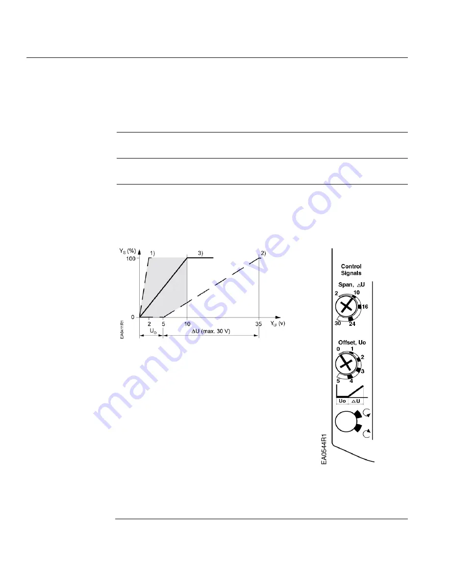
The offset (start point) and span of the control signal can be adjusted. The offset point,
U0, (start point) can be adjusted between 0 to 5 Vdc. The span,
∆
U, can be adjusted
between 2 to 30 Vdc.
Ys
Mechanical positioning range
(100% = angle of rotation 90°)
Yu
Control signal
U0
Offset (start point)
∆
U
Span
1. Uo =0V,
∆
U = 2V
Minimum working range
for Ys = 100%
2. Uo = 5V,
∆
U = 30V Maximum working range
for Ys = 100%
3. Uo = 0V,
∆
U
≈
10V Factory setting
Setting for
10V span
0 offset
Figure 15. Minimum, Factory Setting, and
Maximum Control Signal Adjustment.

