background image

OpenAir™ GCA Series Spring Return 160 lb-in Electronic Damper Actuator 

Technical Instructions 


Document No. 155-173P25 


May 19, 2014 

Siemens Industry, Inc. 

Page 13 


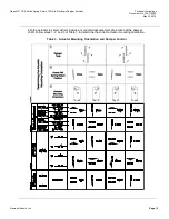
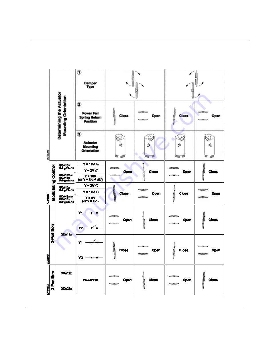
Flip the actuator to select either clockwise or counterclockwise fail-safe rotation of the damper 
shaft. Follow steps 1, 2, and 3 of Table 3 to determine the correct actuator mounting orientation. 

Table 3.  Actuator Mounting Orientation and Damper Control. 


Summary of Contents for OpenAir GCA Series

Page 1: ...ing return Patented self centering shaft coupling Manual override 160 lb in 18 Nm torque 5 preload as shipped from factory Offset and span adjustment models available Models with independently adjustable dual auxiliary switches available UL and cUL listed certified Application These actuators are designed for use in constant or variable air volume installations for the control of return air mixed ...

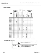
Page 2: ...n Standard Plenum Position Feedback Dual Auxiliary Switches Signal Inversion Offset 0 to 5 Vdc Span 2 to 30 Vdc GCA121 1U GCA121 1P GCA126 1U GCA126 1P GCA221 1U GCA226 1U GCA131 1U GCA131 1P GCA132 1U GCA136 1U GCA136 1P GCA151 1U GCA151 1P GCA156 1U GCA156 1P GCA161 1U GCA161 1P GCA163 1U GCA163 1P GCA164 1U GCA164 1P GCA166 1U GCA166 1P Warning Caution Notations WARNING Personal injury loss of ...

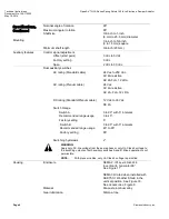
Page 3: ...0 24 Vdc 10 24 Vac 20 24 Vdc 10 120 Vac 10 Frequency 50 60 Hz 50 60 Hz 50 60 Hz 50 60 Hz 50 60 Hz Power Consumption running 7 VA 5W 7 VA 5W 7 VA 5W 7 VA 5W 8 VA holding 5 VA 3W 5 VA 3W 5 VA 3W 5 VA 3W 6 VA Control Signal GCA16x GCA15x GCA13x GCA12x GCA22x Input Signal Y G0 voltage input 0 to 10 Vdc max 35 Vdc 0 to 10 Vdc or 2 to 10 Vdc max 35 Vdc Floating 2 Position 2 Position input resistance 100...

Page 4: ...cable 24 Vac AC 4A resistive AC 2A FLA 12 LRA DC rating Standard Plenum cable 12 Vdc to 30 Vdc DC 2A Switch Range Switch A 0 to 90 with 5 intervals Recommended range usage 0 to 45 Factory setting 5 Switch B 0 to 90 with 5 intervals Recommended range usage 45 to 90 Factory setting 85 Switching hysteresis 2 WARNING Apply only AC line voltage from the same phase or only UL Class 2 voltage to the swit...

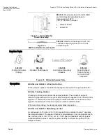
Page 5: ...nsions See Figure 31 Weight 4 85 lb 2 2 kg Actuator Components Figure 1 Modulating GCA Actuator NOTE Not all features are on all models See Table 1 for a listing of features per model Legend 1 Positioning scale for angle of rotation 2 Manual override wrench opening and direction of rotation arrow 3 DIP switches 4 Span adjustment 5 Offset start point adjustment 6 Gear train lock pin 7 Auxiliary swi...

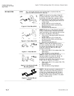
Page 6: ...on into a linear stroke Support bearing ring to minimize side loading on the actuator s output bearing Mounting bracket Required mounting fasteners Figure 4 Crank Arm Kit ASK71 3 Allows direct coupled actuator to provide an auxiliary linear drive Crank arm kit can be used to simultaneously drive a set of opposing or adjacent dampers with single actuator Kit includes Crank arm to attach to the spli...

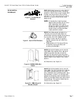
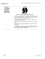
Page 7: ...t the standard self centering adapter will accept up to a one inch 25 4 mm diameter shaft Adapter can be used for coupling to slightly oversized one inch 25 4 mm jackshafts Shaft adapter is 13 16 inches 20 mm shorter than the height of the self centering shaft adapter Figure 9 NEMA 3R Weather Shield ASK75 1U GCA Actuators are UL listed to meet NEMA 3R requirements a degree of protection against ra...

Page 8: ...ion GCA12x and GCA22x 2 Position Control When power is applied the actuator coupling moves toward the open position 90 GCA13x Floating Control A floating control signal controls the damper actuator The actuator s angle of rotation is proportional to the length of time the signal is applied A 24 Vac dc control signal to Y1 causes the actuator coupling to rotate clockwise A 24 Vac dc control signal ...

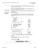
Page 9: ...uator Control Signal Adjustment GCA 163 and GCA164 The offset start point and span of the control signal can be adjusted The offset Uo can be adjusted between 0 to 5 Vdc The span U can be adjusted between 2 to 30 Vdc Ys Mechanical positioning range 100 angle of rotation 90 Yu Control signal Uo Offset start point U Span Uo 0V U 2V The minimum working range for Ys 100 1 Uo 5V U 30V The maximum worki...

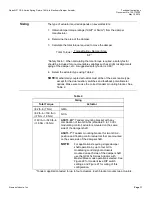
Page 10: ...itches A and B Setting interval 5 Switching hysteresis 2 To change the settings of A and B 1 Make sure the actuator is in the 0 fail safe position The scale is valid only in the 0 position 2 Use a flat blade screwdriver to turn the switch adjustment dials to the desired setting at which a signal is to be given Factory setting Switch A 5 Switch B 85 Figure 16 Dual Auxiliary Switch Dials NOTE For GC...

Page 11: ...for the dual auxiliary switches and feedback potentiometer options Make sure to use the correct tandem mounting bracket See Table 2 Table 2 Sizing Total Torque Actuator 62 lb in 7 Nm GMA 62 lb in 160 lb in 7 Nm 18 Nm GCA 160 lb in 320 lb in 18 Nm 36 Nm ASK73 2U Tandem mounting bracket with any combination of two GCA16x standard 0 to 10 Vdc modulating control actuators mounted on the same side of t...

Page 12: ...er ASK75 1U and outdoor rated conduit fittings Actuator must be in the vertical position The shaft adapter and the position indicator can be mounted on either side of the actuator The actuator mounting orientation and shaft length determine how they will be mounted on the actuator The minimum damper drive shaft length is 3 4 inch 20 mm See Specifications for the minimum and maximum damper shaft di...

Page 13: ...No 155 173P25 May 19 2014 Siemens Industry Inc Page 13 Flip the actuator to select either clockwise or counterclockwise fail safe rotation of the damper shaft Follow steps 1 2 and 3 of Table 3 to determine the correct actuator mounting orientation Table 3 Actuator Mounting Orientation and Damper Control ...

Page 14: ...ill strip the lock pin To release manual override either restore power and send a control signal or when power is absent insert the 3 mm hex key in the override opening turn the key in the direction of the arrow and remove the key Mechanical Range Adjustment The angular rotation is adjustable between 0 and 90 at five degree intervals To limit the range of shaft movement remove the locking clip and...

Page 15: ...must be applied to all six outputs NOTE With plenum cables only UL Class 2 voltage is permitted Implementation of DIP Switch Features GCA15x Only Counterclockwise Self adapt feature 2 to 10 Vdc Tandem Mount Master Clockwise Self Adapt Off 0 to 10 Vdc Single Mount Slave Figure 21 GCA15x Series Self Adapt Feature The factory setting is 0 OFF When mechanical angle of rotation is limited the self adap...

Page 16: ...used in the tandem application one actuator must be identified as the Master by selecting the M on the 5th DIP switch The rest of the actuators used in the application must have the S slave set on the 5th DIP switch Connect all the 2 black Neutral wires and connect them to the power supply Connect all the 1 red Supply wires together and connect them to the power supply The Output Signal 9 pink wir...

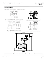
Page 17: ... 19 2014 Siemens Industry Inc Page 17 Wire Designations Each wire has the standard symbol printed on it See Table 4 Figure 23 GCA15x GCA16x Modulating Control Figure 24 GCA12x 2 Position Control Figure 25 GCA13x Floating Control Figure 26 GCA22x 2 Position Control Figure 27 GCA15x 1x for Tandem Application Master Slave ...

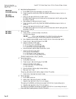
Page 18: ...White red Black P2 Feedback Potentiometer Common B White blue Black P3 Feedback Potentiometer 100 to 0 P3 P2 C White pink Black Start Up Commissioning GCA12x 24 Vac dc GCA22x 120 Vac 1 Check Operation a Switch on Vac dc power b Allow the actuator shaft coupling to rotate from 0 to 90 c Switch off Vac dc power The actuator shaft coupling will return to the 0 position 2 Check Spring Return a Switch ...

Page 19: ...signal 24 Vac dc to wire 6 violet b Allow the actuator shaft coupling to rotate half way c Disconnect wire 1 red d The spring returns the actuator shaft coupling to the fail 0 position e Connect wire 1 red The actuator shaft coupling begins to move 3 Check Feedback a Set the digital multimeter DMM dial to ohms b Connect wires P1 and P2 to the DMM The DMM should indicate a resistive value c Apply a...

Page 20: ...Use a Digital Multimeter DDM and set the dial to Vdc for the actuator input signal c Connect wires 2 black and 8 gray to the DMM d Apply to input signal wire 8 gray Y 10 Vdc or Y Uo U GCA16x Y 10 Vdc GCA15x in direct acting mode Y 2 Vdc GCA15x in inverse acting mode e Allow the actuator shaft coupling to rotate from 0 to 90 f Apply to input signal wire 8 gray Y 0 Vdc or Y Uo GCA16x Y 2 Vdc GCA15x ...

Page 21: ... coupling reaches the setting of switch A 5 Check the Auxiliary Switch B a Set the DMM dial to ohms resistance or continuity check b Connect wires S4 and S6 to the DMM The DMM should indicate open circuit or no resistance c Apply the input signal as in Step 1d to wire 8 gray The DMM should indicate contact closure as the actuator shaft coupling reaches the setting of switch B d Connect wires S4 an...

Page 22: ...res are connected correctly Check that offset start point and span are set correctly if used Use a Digital Multimeter DMM to verify that the operating voltage is within range If the actuator is not working check the damper for blockage If blocked remove the obstacle and cycle the actuator power off and on The actuator should resume normal operating mode Dimensions Figure 29 Dimensions of the ASK75...

Page 23: ...s Schweiz AG Other product or company names mentioned herein may be the trademarks of their respective owners 2014 Siemens Industry Inc Siemens Industry Inc Building Technologies Division 1000 Deerfield Parkway Buffalo Grove IL 60089 4513 USA 1 847 215 1000 Your feedback is important to us If you have comments about this document please send them to sbt_technical editor us sbt siemens com Document...

Reviews: