background image

Document No. 570-11  
Installation Instructions  
February 18, 2013 

Information in this document is based on specifications believed correct at the time of publication. The right is reserved to make changes as 
design improvements are introduced. Product or company names mentioned herein may be the trademarks of their respective owners.  
© 2013 Siemens Industry, Inc.  

Siemens Industry, Inc. 
Building Technologies Division 
1000 Deerfield Parkway 
Buffalo Grove, IL 60089-4513 
USA 

Your feedback is important to us. If you have 
comments about this document, please send them 
to SBT_technical.editor.us.sbt@siemens.com. 

Document No.570-111  

Printed in the USA 

Page 4 of 4  


ODP Driver Installation 

  Obtain the driver files from one of the following 

locations and copy the folder locally to your hard 

drive:  

-  Technical Support Web site, choose the 

Critical Environment patches link. 

-  Standard Apps  

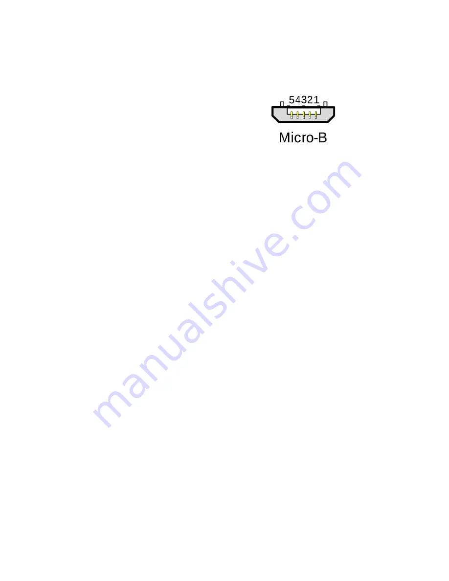
A Micro-B USB cable is required for communication. 

The suggested length of Micro-USB cable should be 

6 foot in length. Below is a picture representation of 

the Micro-B USB cable. Note that the Micro-A USB 

cable style will not work. 


Summary of Contents for Operator Display Panel II

Page 1: ... or without existing cutouts Designed for wall mounting A A conduit box is optional Base plate B has screw holes for all commercially available conduit boxes The height of the screw heads must not exceed 3 mm Device C incorporates a plug an LCD panel emergency purge and horn silence buttons Product Number 575 820A Required Tools For fume hood with an existing cutout you need Medium Phillips head s...

Page 2: ... 2 Drill the two mounting holes using a 3 16 inch 5 mm bit 3 Cut the controller interface port clearance hole using a 1 1 2 inch 38 mm hole saw Installing the ODP 1 Position the mounting bracket over the existing cutout on the fume hood Align the holes on the mounting bracket with the screw holes of the cutout NOTE Make sure that there is enough clearance for the controller interface port on the O...

Page 3: ...ns Industry Inc Page 3 of 4 6 Connect the power module to the ODP and Fume Hood Controller The installation is complete Dismounting the ODP 1 Push the locking tab with a screwdriver until it releases 2 Remove the display fro the mounting plate Mounting plate dimensions ...

Page 4: ...L 60089 4513 USA Your feedback is important to us If you have comments about this document please send them to SBT_technical editor us sbt siemens com Document No 570 111 Printed in the USA Page 4 of 4 ODP Driver Installation Obtain the driver files from one of the following locations and copy the folder locally to your hard drive Technical Support Web site choose the Critical Environment patches ...

Reviews: