Installation Instructions
The following instructions are for the installation of Siemens replacement part connector kits in a Revised P1
panelboard. The parts provided in this kit are for connection to a 1-phase 2 or 3-wire system or a 3-phase 3 or
4-wire system for BL / BQD / GB Type breakers.
11-A-1119-01 Rev. 00
-3-
-2-
DANGER
Hazardous voltage.
Will cause death or
serious injury.
Keep out.
Qualified personnel only.
Disconnect and lock off all
power before working on
this equipment.
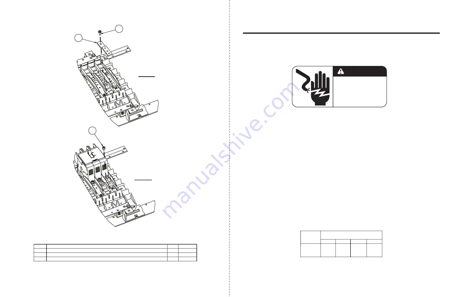
A/C-PHASE CONNECTOR
6
#10-24 x 9/16” HEX WASHER HEAD SCREW
#10-32 x 5/16” HEX HEAD SEMS* ASSEMBLY SCREW
1
2
3
THIS KIT CONTAINS THE FOLLOWING ITEMS:
ITEM
QTY
DESCRIPTION
3
1.
Lock off all power supplying this equipment
before working on it.
4. These connectors are specifically for the
A-phase & C-phase connections. For each
proper position, attach the phase connector
(item 1) to the phase bus using #10-24 hex
washer head screws (item 2) as shown in Fig. 1.
2. Remove the deadfront.
12
6
1
2
5. If the system is 3-phase, B-phase connectors
must be installed prior to any breaker
installation on the following step. (B-phase
connectors available in a separate kit.)
6. Once all necessary connectors are installed,
install proper breaker (for system; not provided),
using #10-32 SEMS assembly screws (item 3)
as shown in Fig. 2.
8. Attach the main cables to the breaker and torque
connections to values specified on the device.
If no values are listed on the device, refer to the
Hardware Tightening Torque label affixed to the
rear of the deadfront.
9.
Before energizing the panel, ensure that all
connections have been properly torqued,
that the deadfront is installed and that all
fillers are in place.
7. Torque all connections to the values specified
on the Hardware Tightening Torque label
affixed to the rear of the deadfront.
3. Remove any/all A-phase & C-phase connectors
that are being replaced by the new parts in this
kit. (Breakers will need to be removed
for access to connectors, if installed.)
N/A
TORQUE
20 lb-in
**
** See torque table on next page
#10-24
25
3/16” AL
1/8” CU
Thread
Size
30
Torque (lb-in) per Bus Material
3/16” CU 1/4” AL
50
30
* SEMS assembly screws have a captive washer on the screw
FIG. 2
FIG. 1


