background image


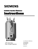
Installation / Operation / Maintenance 

Instructions 


JFR Distribution 
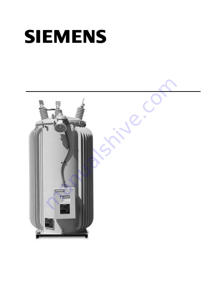
Step Voltage Regulator 

21-115532-001 PR4018-06 

SUPERCEDES 
21-115532-001 
PR4018-05 

October 08 

Summary of Contents for PR4018-04

Page 1: ...Installation Operation Maintenance Instructions JFR Distribution Step Voltage Regulator 21 115532 001 PR4018 06 SUPERCEDES 21 115532 001 PR4018 05 October 08 ...

Page 2: ......

Page 3: ...Components 16 Position Indicator 17 Type TLG Dial Switch 18 Type TLG Quick Break Mechanism 19 Type TLF Dial Switch 20 Type TLF Quick Break Mechanism 21 Bypass Arresters 22 Bushings 23 For Emergency Service Call 1 877 742 3309 Siemens Energy Inc THESE INSTRUCTIONS DO NOT PURPORT TO COVER ALL DETAILS OR VARIATIONS IN EQUIPMENT NOR TO PROVIDE FOR EVERY POSSIBLE CONTINGENCY TO BE MET IN CONNECTION WIT...

Page 4: ......

Page 5: ...fety practices c Is trained in rendering first aid Distinctive signal words DANGER WARNING CAUTION are used in this instruction book to indicate degrees of hazard that may be encountered by the user For the purpose of this manual and product labels these signal words are defined below DANGER Indicates an imminently hazardous situation which if not avoided will result in death or serious injury WAR...

Page 6: ...ling in shipment Should any short age or damage be found notify the local agent of the carrier making the delivery and make appropriate notation on the freight bill Any damage or shortage that is not noted on the freight bill becomes the recipients responsibility A claim should be made immediately with the carrier Please also notify your Siemens representative as soon as possible Assure that the c...

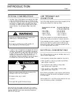
Page 7: ...68A 2 to 800 MCM 669A to 1200A 1 125 12 UNF 2A 1201 A to 2000A 1 500 12 UNF 2A Clamp type terminals for use through 668 ampere are capable of accepting an aluminum or copper conductor Tank grounding provision consists of a 0 5 13NC tapped hole in a steel pad for regulators rated to 300 amperes Above 300 ampere ratings a stainless steel pad with two 0 5 13NC tapped holes is provided ELECTRICAL CONS...

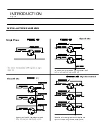
Page 8: ...ounded line Connection of one single phase JFR regulator on single phase line Connection of three JFR regulators in closed delta on three phase ungrounded system Connection of three single phase JFR regulators in wye on a three phase grounded neutral system Open Delta Closed Delta Wye Connected Single Phase 4C Page 4 ...

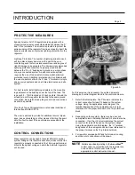
Page 9: ...er condition of thru faults per ANSI C57 15 The user is advised to provide for additional source imped ance bus sectionalizing or other means of limiting the avail able thru fault current if these criteria are exceeded at the installation CONTROL CONNECTIONS Many regulators can be used at several different nominal system voltages It is therefore necessary to assure that the regulator is properly c...

Page 10: ...raight design units may or may not be equiped with a balance winding Refer to regulator nameplate Schematic diagram of a typical Type A JFR regulator with fan power circuit U3 U5 Note Other typical motor supply configurations below Wiring diagram of a typical Type A regulator showing both internal and external connections without fan power Page 6 ...

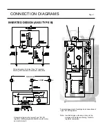
Page 11: ...g both internal and external connections Schematic diagram of a typical Type B JFR regulator utilizing single potential source for motor and control circuit Typical arrangement of windings and connections of Type B JFR regulators Note Inverted design units may or may not be equiped with a balance winding Refer to regulator nameplate ...

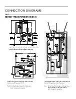
Page 12: ...ram of a typical regulator with series transformer with fan power U3 U5 Note Exciting Winding may not be fully tapped Refer to regulator nameplate SERIES TRANSFORMER DESIGN Typical arrangement of windings and connections of Series JFR regulators without fan power Note Series Transformer design units may or may not be equiped with a balance winding Refer to regulator nameplate ...

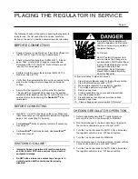
Page 13: ...ill cause serious injury death or equipment damage Do NOT place into service unless tap changer is in neutral position AND control panel is properly disabled Improper By Pass operation will result in explosion and fire hazard Will cause serious injury death or equipment damage To Prevent Do NOT install OR remove from service unless Tap Changer is in neutral position AND Control Panel is properly d...

Page 14: ...ollow instructions to remove from service 1 Place the Auto Manual switch in the By Pass position 2 Place the Raise Lower switch in Off 3 Make certain regulator is in neutral N position If independent checks of the position indicator and NeutraliteTM indicator do not confirm the neutral position bypassing must not be attempted In such event de energize the system to remove the regulator from servic...

Page 15: ...open the circuit Note If the limit switch is set at the maximum 10 range and fails to function the tapchanger will stall against a mechanical stop The motor is designed to stall continuously without damage WARNING Failure to properly maintain the regulator can result in serious injury death or equipment damage The instructions contained herein should be carefully reviewed understood and followed T...

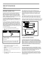
Page 16: ...s on the tapchanger Since numerous factors influence the rate of contact tip wear no one criteria can be stated to recommend when a contact should be changed The following figure shows the possible condition of contact wear after a period of operation If the contact surface is less than 1 8 inch wide the contact should be replaced See the Figure below Contacts both movable and stationary show norm...

Page 17: ... of 18 25 and 30 feet incorporating oil and moisture resistant color coded conductors The Vari Amp TM feature provides a method of operating the regulator at increased load by decreasing the range of op eration It provides operator flexibility by allowing the range of regulation to be adjusted in 1 percent increments The various regulation ranges together with the corresponding current capacities ...

Page 18: ...144 0 100 110 120 135 160 10 14 4 288 0 200 220 240 270 320 10 14 4 333 0 231 254 277 312 370 10 14 4 432 0 300 330 360 405 480 10 14 4 576 0 400 440 480 540 640 11 14 4 720 0 500 550 600 668 668 10 14 4 833 0 578 636 668 668 668 10 19 9 100 0 50 55 60 68 80 10 19 9 200 0 100 110 120 135 160 10 19 9 333 0 167 184 201 226 268 10 19 9 400 0 200 220 240 270 320 10 19 9 667 0 335 368 402 452 536 11 19...

Page 19: ... 21 through 49 inches for most JFR regulators The proper height is selected by picking the elevation that will provide required clearance from foundation to the live part of the regulator bushing The switches are normally set to start the fans at 65 C and to stop them at 55 C top oil temperature but may be adjusted plus or minus 5 C A thermal overload relay is mounted on each fan motor Any fan tha...

Page 20: ...tc All shipments will be made F O B Factory Item 01 11 Description 5050A Control Compartment Gasket 5079 Position Indicator 5081 Main Cover Gasket 5083 Pressure Relief Valve 5084 Terminal Box Gasket 5085 Nameplate 5087 Sampling Device 5088 Grounding Lug Terminal not shown 5092 Terminal Block Clamp 5094B Terminal Block Studs 5095 Terminal Block Gasket 5246 Motor Capacitor TLG 5287 Motor Capacitor T...

Page 21: ...ntact L 5324 Neutral Stationary Contact 5325 Collector Ring 5326 Collector Hub 5327 Reversing Switch Arm Item 01 11 Description 5328A Reversing Switch Finger Assembly 5328B Reversing Switch Hub Finger Assembly 5329 Drive Arm 5330 Hub Finger Support 5331 Ring Finger Support 5332 Main Moving Finger Assembly 5333 Hub Finger Assembly 5334 Ring Finger Assembly 5336 Phenolic Drive Pin Page 17 ...

Page 22: ... Interlock Disk And Drive Assembly 5229 Main Shaft w Sleeve Bearing 5231 Motor Mounting Bracket 5233A Operation Counter Switch Assembly 5234 Roller Chain Position Indicator 5237 Reversing Switch Shaft Item 01 11 Description 5238 Reversing Switch Assembly 5240 Spring 5241 Spring Tube 5242 Position Indicator Drive Mechanism 5243A Neutral Switch 5244 Index Plate 5245A Motor Sprocket 5246 Capacitor fo...

Page 23: ...Ring 5357 Shaft Assembly 5358A Main Finger Assembly each 5359 Contact Finger Assembly Collector Ring 5360A Contact Finger Assembly Collector Hub Item 01 11 Description 5363 Drive Plate 5364 Contact Finger Assembly Rev Switch 5365 Contact Support Assembly 5366 Reversing Drive Pin 5367 Reversing Shaft 5368 Spacer 5369 Contact Finger Support 5370 Contact Finger Support 5373 Reversing Switch Stop Page...

Page 24: ...Motor Capacitor may be located in control box 5288 Actuating Disc and Sprocket 5289 Main Drive Chain 5290 Position Indicator Drive Mechanism 5291 Reversing Switch Spring Assembly 5600 Flexible Shaft 5600A Flexible Shaft O Ring Item 01 11 Description 5233A Counter Switch Assembly 5243B Neutral Switch 5251 Mounting Frame 5252 Motor 5256 Drive Spring Tube 5257 Drive Spring 5259 Spacer 5260 Notched In...

Page 25: ...yp a s s A r r e s t e r A s s e m b l y 3 k V M O V 1 2 0 0 0 1 3 8 0 0 1 4 4 0 0 5425 Mo u n t i n g B r a c k e t A s s e mb l y 5428 B yp a s s A r r e s t e r A s s e mbl y 6 k V M O V 1 9 9 2 0 5429 Mo u n t i n g B r a c k e t A s s e mb l y Include regulator serial number when ordering replacement parts Figure 22B Polymer arresters now used on voltage regulators Supersedes previous porcela...

Page 26: ...2500 414 13 800 5401P Bushing Porcelain for 15 kV 50 5000 38 1 thru 76 2 7620 69 thru 138 13 800 5401R Bushing Porcelain for 15 kV 50 2500 100 5000 5401S Bushing Porcelain for 15 kV 114 3 thru 167 7620 5410 Clamping Ring for 5400 and R Ratings 75 2500 5419 Clamping Ring for 5400S Rating 414 13800 5411 Cushion Spring 5418 Cap Screw 5426 Bushing Cap Line Terminal for 5430 5400P Rating Bushing Cap Li...

Page 27: ...00 5401V Bushing Porcelain 23 kV 72 thru 144 14 400 100 thru 200 19 920 5401W Bushing Porcelain 15 kV 250 thru 416 3 2500 250 thru 416 3 5000 5401X Bushing Porcelain 23 kV 576 thru 833 14 400 5401Y Bushing Porcelain 23 kV 288 14 400 333 thru 400 19 920 5401YY Bushing Porcelain 15 kV 333 12 000 5401Z Bushing Porcelain 23 kV 333 thru 432 14 400 5401AB Bushing Porcelain 23 kV 667 thru 833 19 920 5401...

Page 28: ... Inc P O Box 6289 Jackson MS 39288 6289 Phone 601 939 0550 Fax 601 939 3606 ACCU STAT DATA PAK NEUTRALITE and VARI AMP are trademarks of Siemens Energy Inc PR4018 06 PR4018 05 PR4018 04 October 08 PRINTED IN U S A s ...

Reviews: