background image


SITOP PSU300M/300B 


___________________ 
___________________ 
___________________ 
___________________ 
___________________ 
___________________ 
___________________ 
___________________ 
___________________ 
___________________ 
___________________ 
___________________ 


SITOP power supply 


SITOP PSU300M/300B 

Manual 

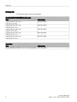
SITOP PSU300M 24 V/20 A 

6EP1436-3BA10 

SITOP PSU300M 48 V/10 A  

6EP1456-3BA00  

SITOP PSU300B 12 V/20 A  

6EP1424-3BA00  

SITOP PSU300B 24 V/17 A  

6EP1436-3BA20  

SITOP PSU300B 24 V/30 A  

6EP1437-3BA20 
  

11.2014 

C98130-A7574-A2-2-7629 

Overview 


Safety notes 


Description, device design, 

dimension drawing 


Mounting/disassembly 


Mounting position, mounting 

clearances 


Installation 


Technical data 


Safety, approvals, EMC 


Ambient conditions 


Applications 


Environment 


10 


Service & Support 


11 

Summary of Contents for PSU300B

Page 1: ...M 300B Manual SITOP PSU300M 24 V 20 A 6EP1436 3BA10 SITOP PSU300M 48 V 10 A 6EP1456 3BA00 SITOP PSU300B 12 V 20 A 6EP1424 3BA00 SITOP PSU300B 24 V 17 A 6EP1436 3BA20 SITOP PSU300B 24 V 30 A 6EP1437 3BA20 11 2014 C98130 A7574 A2 2 7629 Overview Safety notes 1 Description device design dimension drawing 2 Mounting disassembly 3 Mounting position mounting clearances 4 Installation 5 Technical data 6 ...

Page 2: ...operated only by personnel qualified for the specific task in accordance with the relevant documentation in particular its warning notices and safety instructions Qualified personnel are those who based on their training and experience are capable of identifying risks and avoiding potential hazards when working with these products systems Proper use of Siemens products Note the following WARNING S...

Page 3: ...put current are switched on PSU300M and PSU300B 12 V 20 A only Ambient temperature 25 10 70 C 48 V 10 A permits small cable cross sections Selectable short circuit behavior Soft characteristic curve for parallel switching or battery charging can be selected Display of the operating state using 3 LEDs Integrated signaling contact DC 12 V O K DC 24 V O K DC 48 V O K The properties of the PSU300B pow...

Page 4: ...00 500 V AC input Output 24 V DC 20 A 6EP1436 3BA10 3 phase 400 500 V AC input Output 48 V DC 10 A 6EP1456 3BA00 3 phase 400 500 V AC input Output 12 V DC 20 A 6EP1424 3BA00 3 phase 400 500 V AC input Output 24 V DC 17 A 6EP1436 3BA20 3 phase 400 500 V AC input Output 24 V DC 30 A 6EP1437 3BA20 Accessories Type Order number Device identification labels 20 mm 7 mm pastel turquoise 3RT1900 1SB20 ...

Page 5: ...nd weight 17 3 Mounting disassembly 19 4 Mounting position mounting clearances 21 4 1 Standard mounting position 21 4 2 Other mounting positions 24 4 2 1 6EP1436 3BA10 24 4 2 2 6EP1456 3BA00 26 4 2 3 6EP1424 3BA00 28 4 2 4 6EP1436 3BA20 30 4 2 5 6EP1437 3BA20 32 5 Installation 35 5 1 Line side connection 35 5 2 Output side connection 37 6 Technical data 39 6 1 Input 39 6 2 Output 41 6 3 Efficiency...

Page 6: ... Applications 65 9 1 Parallel connection to increase power rating 65 9 2 Parallel connection for redundancy 67 9 3 Series connection for increased voltage 69 9 4 Overload protection in the 24 V output circuit 70 9 5 Protection against short time voltage dips 71 9 6 Protecting against longer power failures 72 9 7 Battery charging with SITOP PSU300B 74 10 Environment 77 11 Service Support 79 ...

Page 7: ...l injury as well as extensive property damage Only appropriately qualified personnel may work on or in the vicinity of this equipment Perfect safe and reliable operation of this equipment is dependent on proper transportation storage installation and mounting Before installation or maintenance work can begin the system s main switch must be switched off and measures taken to prevent it being switc...

Page 8: ...Safety notes SITOP PSU300M 300B 8 Manual 11 2014 C98130 A7574 A2 2 7629 ...

Page 9: ...is available at the output of the device The output of the device is isolated no load proof and short circuit proof The LED displays indicate the operating state The operating state of the device can be processed via the signaling contact The PSU300B devices are optimized to charge batteries Line input DC output Signaling contacts Potentiometer 12 14 V 24 28 8 V 42 56 V Pilot lamps 12 24 48 V OK O...

Page 10: ...ls are used to connect to the loads to be supplied see also Section Installation Page 35 Connections and terminal designations Line input L1 L2 L3 PE One screw terminal each output 2 screw terminals output 2 screw terminals signaling contacts 13 14 One screw terminal each 1 Do not subject the end stop to higher loads Figure 2 2 Terminal data for 6EP1436 3BA10 6EP1456 3BA00 6EP1424 3BA00 6EP1436 3B...

Page 11: ...to the connected load Figure 2 4 Potentiometer example 6EP1456 3BA00 6EP1437 3BA20 NOTICE Thermal overload possible When adjusting the output voltage to 24 V 48 V the output current must be derated by 4 V or the permissible ambient temperature must be taken into account with 3 K V applies to PSU300M devices Note It is only permissible to use an insulated screwdriver when actuating the potentiomete...

Page 12: ...BA00 12 V 20 A 6EP1436 3BA20 24 V 17 A 6EP1437 3BA20 24 V 30 A Operating display LED green for 12 V O K Yellow LED for overload Red LED for latching shutdown LED green for 24 V O K Yellow LED for overload Red LED for latching shutdown Signaling contact Relay contact NO contact rating 60 V DC 0 3 A for 12 V O K Relay contact NO contact rating 60 V DC 0 3 A for 24 V O K Figure 2 5 Operating display ...

Page 13: ...ontact contacts 13 14 open quiescent position Overtemperature power OFF ON after 3 min Overtemperature power OFF ON after 3 min Signaling 6EP1424 3BA00 12 V 20 A 6EP1436 3BA20 24 V 17 A 6EP1437 3BA20 24 V 30 A Green LED lit Signaling contact contacts 13 14 closed Normal operation Output voltage 10 0 V Normal operation output voltage 20 5 V Normal operation output voltage 20 5 V LED off Signaling c...

Page 14: ...1437 3BA20 24 V 30 A Red LED lit Signaling contact contacts 13 14 open quiescent position Latching shutdown only in Shutdown mode Latching shutdown only in Shutdown mode Latching shutdown only in Shutdown mode Red LED flashes Signaling contact contacts 13 14 closed Overtemperature power OFF ON after 3 minutes Overtemperature power OFF ON after 3 minutes Overtemperature power OFF ON after 3 minutes...

Page 15: ... single operation The output voltage is inde pendent of the output current B influences the output characteristic in the overload range Latching shutdown If the output current rises above the rated value and above the current limit the device reduces the output voltage see e g Figure 6 13 6EP1436 3BA10 latching shutdown output characteristic curve Page 48 If the output voltage falls below 10 V 20 ...

Page 16: ...Description device design dimension drawing 2 6 Block diagram SITOP PSU300M 300B 16 Manual 11 2014 C98130 A7574 A2 2 7629 2 6 Block diagram Figure 2 7 Block diagram ...

Page 17: ...ns and weight Figure 2 8 6EP1424 3BA00 6EP1436 3BA20 6EP1436 3BA10 6EP1456 3BA00 dimensioned drawing Figure 2 9 Dimension drawing 6EP1437 3BA20 6EP1424 3BA00 12 V 20 A 6EP1436 3BA20 24 V 17 A 6EP1436 3BA10 24 V 20 A 6EP1456 3BA00 48 V 10 A 6EP1437 3BA20 24 V 30 A Dimensions W H D in mm 70 125 125 150 125 150 Weight approx 1 2 kg approx 3 4 kg ...

Page 18: ...Description device design dimension drawing 2 7 Dimensions and weight SITOP PSU300M 300B 18 Manual 11 2014 C98130 A7574 A2 2 7629 ...

Page 19: ...t on standard mounting rails according to EN 60715 Mounting To mount the device position it with the mounting rail guide at the upper edge of the standard mounting rail and press down to lock it into place If this is too difficult press slider at the same time as described under Removal Removal To remove pull up the slider using a screwdriver and disengage the device at the bottom edge of the stan...

Page 20: ...300B 20 Manual 11 2014 C98130 A7574 A2 2 7629 WARNING Use in hazardous zones If the devices are to be used in hazardous zones Ex II 3G Ex nA nC IIC T4 they must be installed in a distribution box with degree of protection IP54 or higher ...

Page 21: ...the input terminals and the output terminals are at the bottom to ensure correct cooling A clearance of at least 50 mm should be maintained above and below the device maximum depth of the cable duct 50 mm No space is required at the side Output current as a function of the ambient temperature and mounting height Figure 4 1 6EP1436 3BA10 Output current in the standard mounting position Figure 4 2 6...

Page 22: ... PSU300M 300B 22 Manual 11 2014 C98130 A7574 A2 2 7629 Figure 4 3 6EP1424 3BA00 Output current in the standard mounting position Figure 4 4 6EP1436 3BA20 Output current in the standard mounting position Figure 4 5 6EP1437 3BA20 Output current in the standard mounting position ...

Page 23: ...Mounting position mounting clearances 4 1 Standard mounting position SITOP PSU300M 300B Manual 11 2014 C98130 A7574 A2 2 7629 23 Figure 4 6 Mounting height derating ...

Page 24: ... observed in accordance with the following diagrams Note In the case of mounting positions that deviate from the standard mounting position reduced mechanical resistance of the devices against vibration and shock must be expected Particularly when installing on a vertically fastened standard mounting rail additional measures may be required e g to prevent the device from slipping on the standard m...

Page 25: ...rances 4 2 Other mounting positions SITOP PSU300M 300B Manual 11 2014 C98130 A7574 A2 2 7629 25 Figure 4 9 6EP1436 3BA10 mounting position 3 Figure 4 10 6EP1436 3BA10 mounting position 4 Figure 4 11 6EP1436 3BA10 mounting position 5 ...

Page 26: ... Other mounting positions SITOP PSU300M 300B 26 Manual 11 2014 C98130 A7574 A2 2 7629 4 2 2 6EP1456 3BA00 Figure 4 12 6EP1456 3BA00 mounting position 1 Figure 4 13 6EP1456 3BA00 mounting position 2 Figure 4 14 6EP1456 3BA00 mounting position 3 ...

Page 27: ... position mounting clearances 4 2 Other mounting positions SITOP PSU300M 300B Manual 11 2014 C98130 A7574 A2 2 7629 27 Figure 4 15 6EP1456 3BA00 mounting position 4 Figure 4 16 6EP1456 3BA00 mounting position 5 ...

Page 28: ... Other mounting positions SITOP PSU300M 300B 28 Manual 11 2014 C98130 A7574 A2 2 7629 4 2 3 6EP1424 3BA00 Figure 4 17 6EP1424 3BA00 mounting position 1 Figure 4 18 6EP1424 3BA00 mounting position 2 Figure 4 19 6EP1424 3BA00 mounting position 3 ...

Page 29: ... position mounting clearances 4 2 Other mounting positions SITOP PSU300M 300B Manual 11 2014 C98130 A7574 A2 2 7629 29 Figure 4 20 6EP1424 3BA00 mounting position 4 Figure 4 21 6EP1424 3BA00 mounting position 5 ...

Page 30: ... Other mounting positions SITOP PSU300M 300B 30 Manual 11 2014 C98130 A7574 A2 2 7629 4 2 4 6EP1436 3BA20 Figure 4 22 6EP1436 3BA20 mounting position 1 Figure 4 23 6EP1436 3BA20 mounting position 2 Figure 4 24 6EP1436 3BA20 mounting position 3 ...

Page 31: ... position mounting clearances 4 2 Other mounting positions SITOP PSU300M 300B Manual 11 2014 C98130 A7574 A2 2 7629 31 Figure 4 25 6EP1436 3BA20 mounting position 4 Figure 4 26 6EP1436 3BA20 mounting position 5 ...

Page 32: ...mounting clearances 4 2 Other mounting positions SITOP PSU300M 300B 32 Manual 11 2014 C98130 A7574 A2 2 7629 4 2 5 6EP1437 3BA20 Figure 4 27 6EP1437 3BA20 mounting position 1 Figure 4 28 6EP1437 3BA20 mounting position 2 ...

Page 33: ...rances 4 2 Other mounting positions SITOP PSU300M 300B Manual 11 2014 C98130 A7574 A2 2 7629 33 Figure 4 29 6EP1437 3BA20 mounting position 3 Figure 4 30 6EP1437 3BA20 mounting position 4 Figure 4 31 6EP1437 3BA20 mounting position 5 ...

Page 34: ...Mounting position mounting clearances 4 2 Other mounting positions SITOP PSU300M 300B 34 Manual 11 2014 C98130 A7574 A2 2 7629 ...

Page 35: ...ding to VDE 0100 T 300 IEC 364 3 with a rated voltage of 3 phase 400 500 V AC 50 60 Hz IT system with rated voltages 3 phase 400 480 V AC Figure 5 1 Line connection example 6EP1456 3BA00 The line supply is connected using terminals L1 L2 L3 and PE see Figure 5 1 Line connection example 6EP1456 3BA00 Page 35 and must be implemented according to IEC 60364 and EN 50178 A protective device miniature c...

Page 36: ...e coupled miniature circuit breaker IEC 898 characteristic C 6 10 A or 3RV2011 1EA10 circuit breaker setting of the thermal overcurrent trip 3 A or 3RV2711 1DD10 circuit breaker branch circuit protection according to UL 489 6EP1436 3BA20 24 V 17 A 3 pole coupled miniature circuit breaker IEC 898 characteristic C 6 16 A or 3RV2011 1EA10 circuit breaker setting of the thermal overcurrent trip 3 A or...

Page 37: ... 6EP1456 3BA00 6EP1437 3BA20 The output voltage is connected via the and terminals at the output of the power supply see Figure 5 2 Output connection example 6EP1456 3BA00 6EP1437 3BA20 Page 37 Ensure that the output cables are dimensioned correctly for the maximum output current rms value and fused accordingly Note If the safety concept of the plant or system specifies that the DC output circuit ...

Page 38: ...Installation 5 2 Output side connection SITOP PSU300M 300B 38 Manual 11 2014 C98130 A7574 A2 2 7629 ...

Page 39: ...input Yes Yes Overvoltage strength 2 3 Ue rated 1 3 ms 2 3 Ue rated 1 3 ms Power failure buffering at Ia rated min Remark at Ue 400 V 15 ms 15 ms Rated line frequency 50 60 Hz 50 60 Hz Line frequency range 47 63 Hz 47 63 Hz Input current at rated value of input voltage 400 V 1 2 A 1 2 A Input current at rated value of input voltage 500 V 1 A 1 A Inrush current limiting 25 C max 18 A 18 A I t max 0...

Page 40: ...uency 50 60 Hz 50 60 Hz 50 60 Hz Line frequency range 47 63 Hz 47 63 Hz 47 63 Hz Input current at rated value of input voltage 400 V 0 7 A 1 2 A 1 6 A Input current at rated value of input voltage 500 V 0 6 A 1 A 1 3 A Inrush current limiting 25 C max 18 A 18 A 56 A I t max 0 8 A2s 0 8 A2s 2 24 A2s Integrated input fuse None None None Protection in the line feeder cable IEC 898 Required 3 pole cou...

Page 41: ...ng Relay contact NO contact rating 60 V DC 0 3 A for 24 V O K Relay contact NO contact rating 60 V DC 0 3 A for 48 V O K Response when switching on off No overshoot of Ua Soft Start No overshoot of Ua Soft Start Starting delay max 2 5 s 2 5 s Voltage rise typ 150 ms 150 ms Voltage rise time of the output voltage maximum 500 ms 500 ms Rated current value Ia rated 20 A 10 A Current range Remark 0 20...

Page 42: ...kes peak peak max bandwidth approx 20 MHz 200 mV 200 mV 200 mV Adjustment range 12 14 V 24 28 8 V 24 28 8 V Product function output voltage can be adjusted Yes Yes Yes Output voltage setting Remark Via potentiometer Via potentiometer Max 480 W Via potentiometer Operating display LED green for 12 V O K LED green for 24 V O K LED green for 24 V O K Signaling Relay contact NO contact rating 60 V DC 0...

Page 43: ...e 6EP1456 3BA00 6EP1437 3BA20 Page 15 Yes Switchable characteristic curve see Figure 2 6 Selec tor switch example 6EP1456 3BA00 6EP1437 3BA20 Page 15 Yes Switchable characteristic curve see Figure 2 6 Selec tor switch example 6EP1456 3BA00 6EP1437 3BA20 Page 15 Number of devices that can be connected in parallel to increase the power rating units 2 2 2 Output characteristic See Figure 6 5 6EP1424 ...

Page 44: ... Manual 11 2014 C98130 A7574 A2 2 7629 Figure 6 3 6EP1436 3BA10 single operation output characteristic curve Figure 6 4 6EP1456 3BA00 single operation output characteristic curve Figure 6 5 6EP1424 3BA00 single operation output characteristic curve ...

Page 45: ... 6 6 6EP1436 3BA20 single operation output characteristic curve Figure 6 7 6EP1437 3BA20 single operation output characteristic curve The device supplies a constant output voltage until the current limit is reached If overload occurs the output current is limited and the output voltage lowered ...

Page 46: ...A closed parallel operation The output voltage decreases with increasing output current Figure 6 8 6EP1436 3BA10 parallel operation output characteristic curve Figure 6 9 6EP1456 3BA00 parallel operation output characteristic curve Figure 6 10 6EP1424 3BA00 parallel operation output characteristic curve ...

Page 47: ...6 2 Output SITOP PSU300M 300B Manual 11 2014 C98130 A7574 A2 2 7629 47 Figure 6 11 6EP1436 3BA20 parallel operation output characteristic curve Figure 6 12 6EP1437 3BA20 parallel operation output characteristic curve ...

Page 48: ...hut down if the overload continues for longer than 100 ms A reset is performed by switching the power supply OFF for at least 5 seconds Figure 6 13 6EP1436 3BA10 latching shutdown output characteristic curve Figure 6 14 6EP1456 3BA00 latching shutdown output characteristic curve Figure 6 15 6EP1424 3BA00 latching shutdown output characteristic curve ...

Page 49: ... 6 2 Output SITOP PSU300M 300B Manual 11 2014 C98130 A7574 A2 2 7629 49 Figure 6 16 6EP1436 3BA20 latching shutdown output characteristic curve Figure 6 17 6EP1437 3BA20 latching shutdown output characteristic curve ...

Page 50: ... 6EP1456 3BA00 48 V 10 A Efficiency at Ua rated Ia rated approx 93 93 Power loss at Ua rated Ia rated approx 36 W 36 W 6EP1424 3BA00 12 V 20 A 6EP1436 3BA20 24 V 17 A 6EP1437 3BA20 24 V 30 A Efficiency at Ua rated Ia rated approx 88 93 93 Power loss at Ua rated Ia rated approx 20 W 31 W 50 W Figure 6 18 6EP1436 3BA10 efficiency ...

Page 51: ...Technical data 6 3 Efficiency SITOP PSU300M 300B Manual 11 2014 C98130 A7574 A2 2 7629 51 Figure 6 19 6EP1456 3BA00 efficiency Figure 6 20 6EP1424 3BA00 efficiency ...

Page 52: ...Technical data 6 3 Efficiency SITOP PSU300M 300B 52 Manual 11 2014 C98130 A7574 A2 2 7629 Figure 6 21 6EP1436 3BA20 efficiency Figure 6 22 6EP1437 3BA20 efficiency ...

Page 53: ...a typ 2 2 Load step regulation time 50 to 100 typ 2 ms 2 ms Load step regulation time 100 to 50 typ 2 ms 2 ms Regulation time maximum 10 ms 10 ms 6EP1424 3BA00 12 V 20 A 6EP1436 3BA20 24 V 17 A 6EP1437 3BA20 24 V 30 A Dyn line regulation Ue rated 15 max 2 1 1 Dyn load regulation Ia 50 100 50 Ua typ 4 2 3 Load step regulation time 50 to 100 typ 2 ms 2 ms Load step regulation time 100 to 50 typ 2 ms...

Page 54: ...dicator Yellow LED for overload red LED for latching shutdown Yellow LED for overload red LED for latching shutdown 6EP1424 3BA00 12 V 20 A 6EP1436 3BA20 24 V 17 A 6EP1437 3BA20 24 V 30 A Output overvoltage protec tion 35 V 35 V 35 V Current limitation typ 22 A 19 A 32 A Property of the output short circuit proof Yes Yes Yes Short circuit protection Optional constant current characteristic approx ...

Page 55: ...rminals each for 0 2 6 4 mm solid finely stranded 2 screw terminals each for 0 2 6 4 mm solid finely stranded Connections auxiliary contacts 13 14 signaling contact 1 screw terminal each for 0 14 1 5 mm solid finely stranded 13 14 signaling contact 1 screw terminal each for 0 14 1 5 mm solid finely stranded Width of the housing 70 mm 70 mm Height of the housing 125 mm 125 mm Depth of the housing 1...

Page 56: ...6 10 mm solid finely stranded Connections auxiliary con tacts 13 14 signaling con tact 1 screw terminal each for 0 14 1 5 mm solid finely stranded 1 screw terminal each for 0 14 1 5 mm solid finely stranded 1 screw terminal each for 0 14 4 2 5 mm solid finely stranded Width of the housing 70 mm 70 mm 150 mm Height of the housing 125 mm 125 mm 125 mm Depth of the housing 125 mm 125 mm 150 mm Mounti...

Page 57: ...ncy module Mechanical accessories Device identification labels 20 mm 7 mm pastel turquoise 3RT1900 1SB20 6 9 Dimension drawing See Section Dimensions and weight Page 17 CAD data that can be downloaded from the Internet 6EP1436 3BA10 http www automation siemens com bilddb index aspx objKey G_KT01_XX_00459 6EP1456 3BA00 http www automation siemens com bilddb index aspx objKey G_KT01_XX_00568 6EP1424...

Page 58: ...Technical data 6 9 Dimension drawing SITOP PSU300M 300B 58 Manual 11 2014 C98130 A7574 A2 2 7629 ...

Page 59: ...age See Table 7 1 Test voltage Page 60 See Table 7 1 Test voltage Page 60 6EP1424 3BA00 12 V 20 A 6EP1436 3BA20 24 V 17 A 6EP1437 3BA20 24 V 30 A Primary secondary galvanic isolation Yes Yes Yes Electrical isolation SELV output voltage Ua according to EN 60950 1 and EN 50178 SELV output voltage Ua according to EN 60950 1 and EN 50178 SELV output voltage Ua according to EN 60950 1 and EN 50178 Prot...

Page 60: ...t the input terminals with one another Connect the output terminals and PE together Test C Connect the output terminals with one another and measure with respect to PE Table 7 1 Test voltage Test time Prim sec A Prim PE B Sec PE C Type test 60 s 4200 VDC 2200 VDC 700 VDC 60 s 3000 VAC 1500 VAC 500 VAC Production test 1 s 2200 VDC 2200 VDC 500 VDC 1 s 1500 VAC 1500 VAC 350 VAC Field test 1 s 2200 V...

Page 61: ... EG Yes 2004 108 EG and 2006 95 EG UL cUL CSA approval cULus Listed UL 508 CSA C22 2 No 107 1 File E197259 cULus Listed UL 508 CSA C22 2 No 107 1 File E197259 cULus Listed UL 508 CSA C22 2 No 107 1 File E197259 Marine approvals GL 7 4 EMC 6EP1436 3BA10 24 V 20 A 6EP1456 3BA00 48 V 10 A 6EP1424 3BA00 12 V 20 A 6EP1436 3BA20 24 V 17 A 6EP1437 3BA20 24 V 30 A Electrostatic discharge EN 61000 4 2 8 kV...

Page 62: ...2 7629 6EP1436 3BA10 24 V 20 A 6EP1456 3BA00 48 V 10 A 6EP1424 3BA00 12 V 20 A 6EP1436 3BA20 24 V 17 A 6EP1437 3BA20 24 V 30 A Line harmonics limit EN 61000 3 2 Class A Generic standards EN61000 6 2 Noise immunity for industrial environments EN61000 6 3 Emission for residential areas ...

Page 63: ...heat EN 60068 2 78 humid heat constant EN 60068 2 14 temperature change Transport and storage temperature 40 85 C Tests packed for shipping according to EN 60068 2 1 cold EN 60068 2 2 dry heat EN 60068 2 30 humid heat cyclic Humidity class Climatic class 3K3 according to EN 60721 without condensation Mechanical stressing during operation Tested according to EN 60068 2 6 vibration test Fc 0 075 mm ...

Page 64: ...EN 60068 2 43 hydrogen sulfide Atmospheric pressure Operation 1080 795 hPa 1000 2000 m For operation at altitudes of 2000 m up to 6000 m above sea level output must be derated by 7 5 1000 m or the ambient temperature must be reduced by 5 K 1000 m see Figure 4 6 Mounting height derating Page 23 Overvoltage category III to 2000 m EN 50178 II from 2000 m to 6000 m EN 50178 II to 2000 m EN 60950 1 I f...

Page 65: ...ted in parallel must be switched on simultaneously with a common switch in the line feeder cable e g with the main switch available in control cabinets The output voltages measured in no load operation for the power supplies that are not yet connected in parallel should not deviate more than a maximum of 50 mV This usually corresponds to the factory setting If the output voltage is changed you sho...

Page 66: ...han two power supplies When connecting more than two power supplies in parallel additional measures must be taken to prevent high backward feeding currents in the event of a secondary device fault For this purpose a suitable protective circuit e g decoupling diode or DC conform circuit breaker must be installed between each terminal of the power supply and the common connection point ...

Page 67: ...ly takes over the power supply If one of the power supplies fails then this is signaled using an LED on the redundancy module as well as an isolated relay contact For higher output current each power supply must be connected to a redundancy module Figure 9 3 Redundant configuration with two power supplies and two SITOP PSE202U redundancy modules Page 68 When dimensioning the system it must be ensu...

Page 68: ...0M 300B 68 Manual 11 2014 C98130 A7574 A2 2 7629 Figure 9 3 Redundant configuration with two power supplies and two SITOP PSE202U redundancy modules You can find additional information at SITOP PSE202U manual http support automation siemens com WW view en 42248598 ...

Page 69: ... terminal of the first power supply and the terminal of the second power supply are routed to the load Depending on the grounding point of the secondary output voltages voltages of 48 V 24 V or 48 V can be realized In the case of an asymmetric load distribution it is not possible to guarantee correct functionality WARNING SELV is not guaranteed in the case of a fault When connecting two power supp...

Page 70: ...aining 24 V loads The SITOP PSE200U selectivity module with 4 outputs versions with adjustable output current range for each output from 0 5 3 A and 3 10 A is available this monitors the 24 V branches for overload and short circuits Figure 9 5 Selectivity module Page 70 Brief current peaks e g as a result of a high inrush current are permitted and branches with a longer overload are switched into ...

Page 71: ... the power supply reliability it may make sense to increase the line buffering time in the device using an additional SITOP PSE201U buffer module The SITOP PSE201U buffer module based on electrolytic capacitors is connected in parallel to the 24 V power supply output Figure 9 6 Buffer module Page 71 The buffer time is 200 ms at 40 A up to 1 6 s for a load current of 5 A This time can be increased ...

Page 72: ...wer supply failures up into the minutes range can be buffered using the maintenance free SITOP UPS500 DC UPS modules based on capacitors Figure 9 7 24 V buffering to allow the saving of process data and controlled shutdown of PCs Page 72 Figure 9 7 24 V buffering to allow the saving of process data and controlled shutdown of PCs Using the free of charge SITOP DC UPS software tool DC UPS systems ca...

Page 73: ...1600 to maintain communication signaling functions sensor measured values and position values For open PC based automation systems configuration and monitoring is realized using the SITOP UPS Manager PC software which is available at no charge This allows PC responses to the operating states of the DC UPS to be freely selected and offers comprehensive diagnostic functions For TIA based automation ...

Page 74: ... 6 11 6EP1436 3BA20 parallel operation output characteristic curve Page 47 Figure 6 12 6EP1437 3BA20 parallel operation output characteristic curve Page 47 Note The value recommended by the battery manufacturer dependent on the accumulator temperature must be set as end of charge voltage A lead accumulator temperature of 20 to 30 C is ideal in this case the recommended end of charge voltage is nor...

Page 75: ...tact 13 14 closed Battery voltage approx 10 V or approx 20 V Yellow LED overload lights Signaling contact 13 14 open Battery voltage approx 10 V or approx 20 V Figure 9 9 Battery charging with SITOP PSU300B WARNING The SITOP PSU300B power supply is a built in device It must be installed in a housing or control cabinet to which only qualified personnel have access If SITOP is used as the battery ch...

Page 76: ...Applications 9 7 Battery charging with SITOP PSU300B SITOP PSU300M 300B 76 Manual 11 2014 C98130 A7574 A2 2 7629 ...

Page 77: ... Environment 10 The devices are in conformance with RoHS As a rule only non silicon precipitating materials are used Disposal guidelines Packaging and packaging aids can and should always be recycled The product itself may not be disposed of as domestic refuse ...

Page 78: ...Environment SITOP PSU300M 300B 78 Manual 11 2014 C98130 A7574 A2 2 7629 ...

Page 79: ...lies is available in the Internet at the SITOP homepage SITOP http www siemens de sitop Information material SITOP information can be downloaded from the Internet Information and download center http www siemens de sitop infomaterial CAx data 2D 3D data and circuit diagram macros can be downloaded from the Internet Siemens image database http www siemens de sitop cax Request all CAx data via the C...

Page 80: ... 7629 Contact persons If you have any questions regarding the use of our products then contact the Siemens contact person in your regional Siemens sales office You can find these addresses as follows On the Internet http www siemens de automation partner In Catalog CA 01 ...

Reviews: